Our Products
Comprehensive industrial automation solutions for global industries
Contact us
If you are interested in our products and want to know more details,please Contact us,we will reply you as soon as we can.
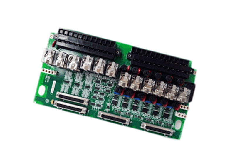
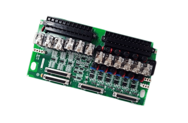


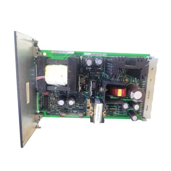
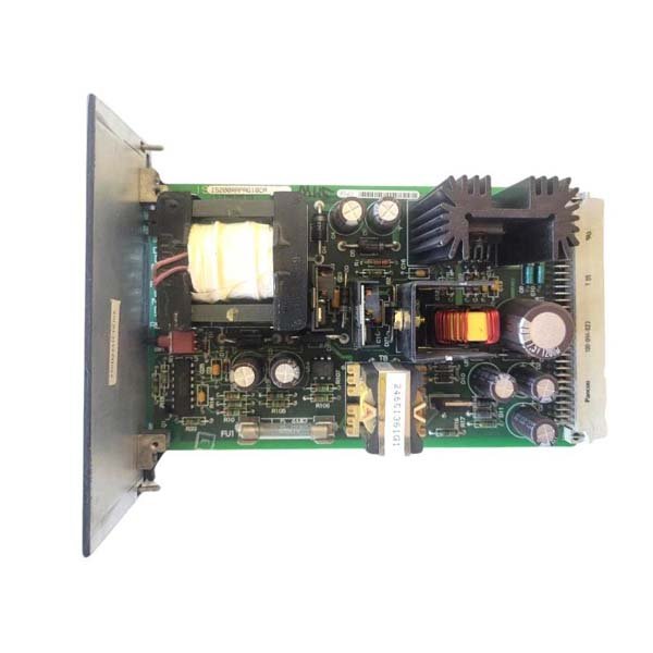
General Electric IS200RAPAG1BCA Relay/Protection Interface Module
Manufacturer:GE Fanuc
Product Number:IS200RAPAG1BCA
Product Type:Relay/Protection Interface Module
Origin:USA
Dimensions:178 mm × 110 mm × 38 mm
Weight:0.72 kg
Views:107
Payment Methods:T/T, PayPal, Western Union
Condition:New & In Stock
Warranty:1 Year
Lead Time:1-3 Working Days
Certificate:COO
Courier partners:DHL, UPS, TNT, FedEx and EMS.
Business hours:7*24
Product Description
The IS200RAPAG1BCA serves as a protection and relay interface component within GE Mark VI/VIe architectures. Its primary task is to receive critical protection inputs and deliver relay-based actions to enforce shutdown, interlock, or safety responses. In troubleshooting environments, technicians rely on the stability of this module to confirm whether protective signals are passing correctly through the system.
Technical Characteristics and Physical Dimensions
| Feature | Details |
|---|---|
| Brand | GE |
| Module Type | Relay/Protection Interface Module |
| Functional Inputs | Multiple opto-isolated protective signals |
| Relay Outputs | Protection command pathways |
| Rated Voltage | 24V DC |
| Isolation Strength | 2 kV |
| Dimensions (L × W × H) | 178 mm × 110 mm × 38 mm |
| Weight | 0.72 kg |
| Operating Temperature | -20°C to 65°C |
| Storage Temperature | -40°C to 85°C |
Preliminary Checks Before Troubleshooting
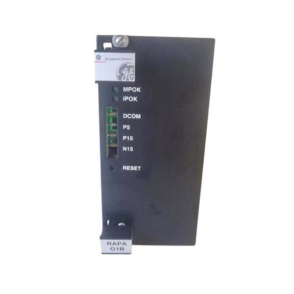
Before entering fault isolation steps, technicians must confirm several prerequisites. The module should be firmly seated in the backplane, all wiring harnesses must be fully engaged, and the protective circuits must be free of unintended grounds. LED activity on the board often provides the first clue about abnormal input conditions.
If a relay fails to respond, technicians are instructed to verify the upstream protective signal source before attempting module-level diagnosis.
Signal Path Verification Procedures
When a mismatch occurs between a protective event and the response of downstream equipment, the module is evaluated in the following logical sequence (without numbering for instructional fluidity):
-
Verify that opto-isolated input channels receive correct triggering voltage.
-
Inspect the LED indicators to confirm input energization or loss.
-
Measure the relay coil voltage using a digital multimeter to validate actuation.
-
Confirm that output relays are not mechanically stuck or contaminated by debris.
-
Inspect the wiring terminals for reversed polarity or loose screws.
-
Observe for thermal damage or discoloration near high-current paths.
These steps are frequently used in high-risk shutdown circuits where a delayed relay response can compromise equipment integrity.
Operational Use Cases
The IS200RAPAG1BCA appears in systems requiring deterministic protective actions such as:
-
Turbine trip signal distribution
-
Emergency lube-oil shutdown systems
-
Overspeed logic handling
-
Auxiliary equipment interlock enforcement
-
Redundant protection chains for high-availability installations
In fault investigations, this module is often one of the first points examined due to its central role in safety-related pathways.
Reasons Technicians Rely on This Module
-
Clear LED state indicators that simplify early diagnosis
-
Robust isolation preventing noise from corrupting protection paths
-
Relay hardware proven to withstand continuous cycling
-
Fast actuation appropriate for trip-class protection events
-
Mechanical reliability in vibration-intensive environments
-
Straightforward wiring, reducing interpretation errors during inspections
Frequently Asked Questions (FAQ)
-
Does the module require periodic relay replacement?
Normally no; relays are rated for long-term service unless exposed to abnormal loads.
-
Are the protection inputs fully isolated?
Yes, each input is opto-isolated to prevent electrical interference.
-
Can the board operate normally with minor backplane voltage fluctuations?
Yes, as long as voltage remains within GE-specified tolerances.
-
What does a continuously lit input LED indicate?
It typically signals persistent input voltage or a stuck external sensor.
-
Can relay outputs fail without visible symptoms?
Rarely, but coil resistance testing can confirm internal faults.
-
How should technicians verify a trip signal?
By checking both LED activity and relay continuity during simulated trip conditions.
-
Does the module support redundant protection chains?
Yes, it integrates cleanly with dual or triple redundant architectures.
-
Is temperature-induced drift a concern?
The board is stable across its full operating temperature range.
-
Can wiring errors cause intermittent faults?
Yes, especially improper grounding or reversed polarity on input lines.
-
Is cleaning required for preventive maintenance?
Only dry brushing or compressed air; moisture and solvents must be avoided.
 Loading comments...
General Electric IS200RAPAG1BCA Relay/Protection Interface Module
Manufacturer:GE Fanuc
Product Number:IS200RAPAG1BCA
Product Type:Relay/Protection Interface Module
Origin:USA
Dimensions:178 mm × 110 mm × 38 mm
Weight:0.72 kg
Views:107
Payment Methods:T/T, PayPal, Western Union
Condition:New & In Stock
Warranty:1 Year
Lead Time:1-3 Working Days
Certificate:COO
Courier partners:DHL, UPS, TNT, FedEx and EMS.
Business hours:7*24
Product Description
The IS200RAPAG1BCA serves as a protection and relay interface component within GE Mark VI/VIe architectures. Its primary task is to receive critical protection inputs and deliver relay-based actions to enforce shutdown, interlock, or safety responses. In troubleshooting environments, technicians rely on the stability of this module to confirm whether protective signals are passing correctly through the system.
Technical Characteristics and Physical Dimensions
| Feature | Details |
|---|---|
| Brand | GE |
| Module Type | Relay/Protection Interface Module |
| Functional Inputs | Multiple opto-isolated protective signals |
| Relay Outputs | Protection command pathways |
| Rated Voltage | 24V DC |
| Isolation Strength | 2 kV |
| Dimensions (L × W × H) | 178 mm × 110 mm × 38 mm |
| Weight | 0.72 kg |
| Operating Temperature | -20°C to 65°C |
| Storage Temperature | -40°C to 85°C |
Preliminary Checks Before Troubleshooting
Before entering fault isolation steps, technicians must confirm several prerequisites. The module should be firmly seated in the backplane, all wiring harnesses must be fully engaged, and the protective circuits must be free of unintended grounds. LED activity on the board often provides the first clue about abnormal input conditions.
If a relay fails to respond, technicians are instructed to verify the upstream protective signal source before attempting module-level diagnosis.
Signal Path Verification Procedures
When a mismatch occurs between a protective event and the response of downstream equipment, the module is evaluated in the following logical sequence (without numbering for instructional fluidity):
-
Verify that opto-isolated input channels receive correct triggering voltage.
-
Inspect the LED indicators to confirm input energization or loss.
-
Measure the relay coil voltage using a digital multimeter to validate actuation.
-
Confirm that output relays are not mechanically stuck or contaminated by debris.
-
Inspect the wiring terminals for reversed polarity or loose screws.
-
Observe for thermal damage or discoloration near high-current paths.
These steps are frequently used in high-risk shutdown circuits where a delayed relay response can compromise equipment integrity.
Operational Use Cases
The IS200RAPAG1BCA appears in systems requiring deterministic protective actions such as:
-
Turbine trip signal distribution
-
Emergency lube-oil shutdown systems
-
Overspeed logic handling
-
Auxiliary equipment interlock enforcement
-
Redundant protection chains for high-availability installations
In fault investigations, this module is often one of the first points examined due to its central role in safety-related pathways.
Reasons Technicians Rely on This Module
-
Clear LED state indicators that simplify early diagnosis
-
Robust isolation preventing noise from corrupting protection paths
-
Relay hardware proven to withstand continuous cycling
-
Fast actuation appropriate for trip-class protection events
-
Mechanical reliability in vibration-intensive environments
-
Straightforward wiring, reducing interpretation errors during inspections
Frequently Asked Questions (FAQ)
-
Does the module require periodic relay replacement?
Normally no; relays are rated for long-term service unless exposed to abnormal loads.
-
Are the protection inputs fully isolated?
Yes, each input is opto-isolated to prevent electrical interference.
-
Can the board operate normally with minor backplane voltage fluctuations?
Yes, as long as voltage remains within GE-specified tolerances.
-
What does a continuously lit input LED indicate?
It typically signals persistent input voltage or a stuck external sensor.
-
Can relay outputs fail without visible symptoms?
Rarely, but coil resistance testing can confirm internal faults.
-
How should technicians verify a trip signal?
By checking both LED activity and relay continuity during simulated trip conditions.
-
Does the module support redundant protection chains?
Yes, it integrates cleanly with dual or triple redundant architectures.
-
Is temperature-induced drift a concern?
The board is stable across its full operating temperature range.
-
Can wiring errors cause intermittent faults?
Yes, especially improper grounding or reversed polarity on input lines.
-
Is cleaning required for preventive maintenance?
Only dry brushing or compressed air; moisture and solvents must be avoided.
Need a Custom Automation Solution?
Our team of experts can design and implement a tailored automation system to meet your specific requirements.