Our Products
Comprehensive industrial automation solutions for global industries
Contact us
If you are interested in our products and want to know more details,please Contact us,we will reply you as soon as we can.
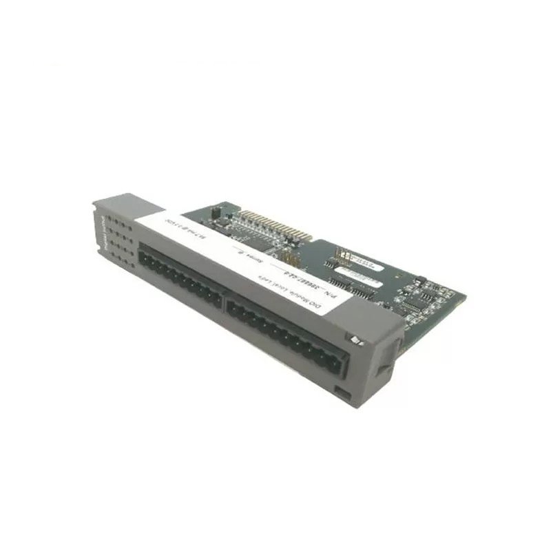
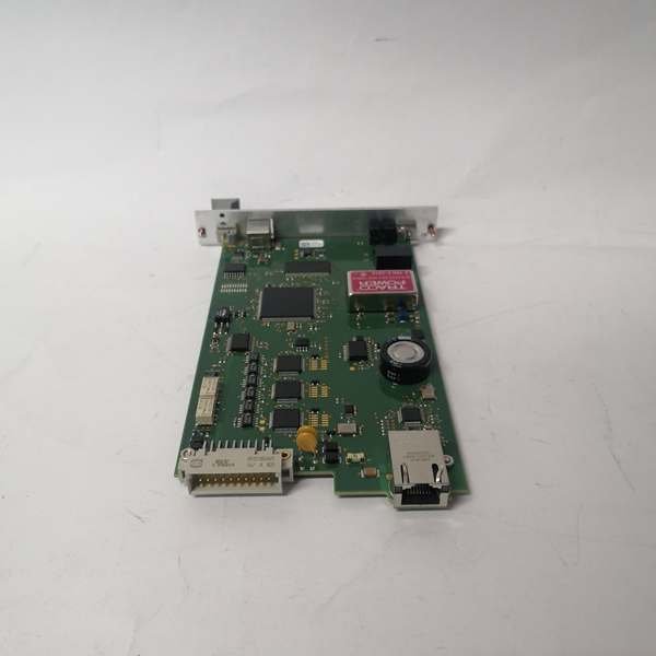
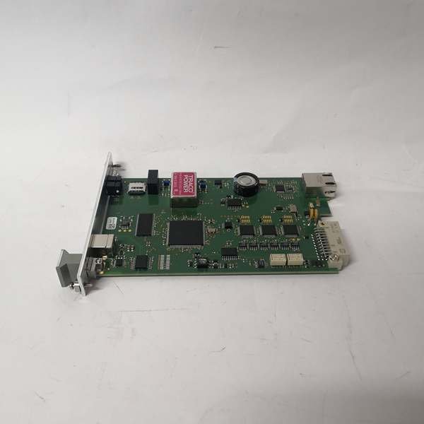
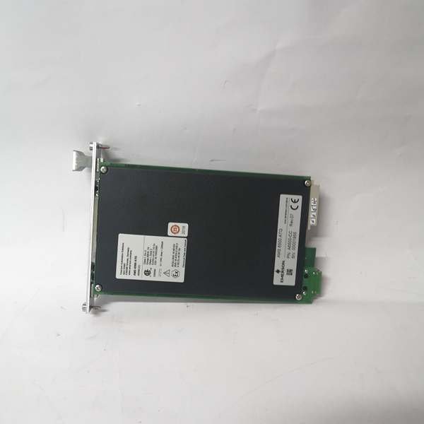
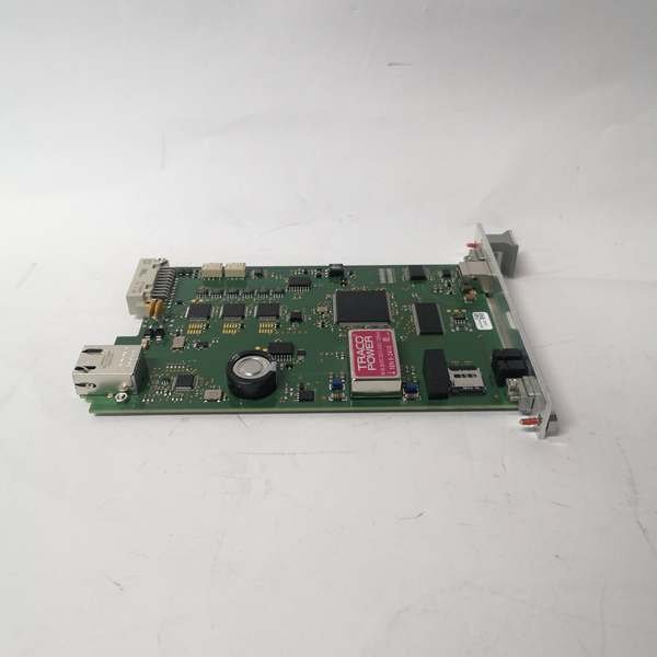
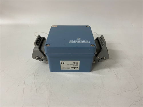
Emerson A6500-CC I/O Chassis Manager
Manufacturer: Emerson
Product Number: A6500-CC (9199-00120)
Category: I/O Chassis Manager (A6500 Series)
Processor: Dual-core Arm Cortex-A9
Function: Manages backplane communication, processes channel data, executes diagnostics
Operating Temperature: -40°C to +70°C
Application: A6500 I/O chassis control and management
Product Description
The A6500-CC 9199-00120 is a purpose-built chassis controller engineered to manage A6500 I/O chassis with uncompromised reliability and speed. At its core is a dual-core Arm Cortex-A9 processor: one core handles backplane communication (routing data between I/O modules and the DCS), while the other manages chassis diagnostics, redundancy logic, and power monitoring. This distributed processing ensures that high backplane traffic (e.g., 32 modules sending 16 channels each) doesn’t slow down critical tasks like failover or fault detection.
Key Technical Specifications
- Model Number: A6500-CC 9199-00120
- Manufacturer: Emerson Automation Solutions
- Function: Chassis Management, I/O Module Orchestration, DCS Communication Gateway
- Redundancy: 1:1 Hot-Standby (With A6500-CR Partner), Automatic Failover <3ms
- Backplane Protocol: A6500 Proprietary High-Speed Backplane (Up to 500 Mbps)
- DCS Communication: Ovation Backplane Protocol, Modbus TCP/IP, HART Pass-Through
- Supported I/O Modules: A6500-UM (Universal I/O), A6500-AI (Analog Input), A6500-DO (Digital Output)
- Operating Temperature: -40°C to 70°C (-40°F to 158°F)
- Isolation: 2500V DC Chassis-to-Backplane, 1500V DC Communication Ports
- Power Consumption: 15W Typical, 22W Maximum (From Chassis)
- Mounting: 1U A6500 Chassis Slot (Slot 1 Dedicated), Tool-Less Latching
- Protection Features: Overvoltage, Overcurrent, Thermal Shutdown, ESD Protection (±8kV Contact)
- Certifications: UL 61010-1, CSA C22.2 No. 61010-1, IEC 61131-3, CE, RoHS
- Compatibility: A6500 16-Slot/32-Slot I/O Chassis, Ovation DCS v4.0+, DeltaV DCS (With Adapter)
Field Application & Problem Solved
In industrial I/O chassis systems—power plant boiler control racks, refinery process skids, chemical reactor I/O banks—the chassis controller is the “traffic cop” that routes data between I/O modules and the DCS. Legacy non-redundant chassis controllers were a single point of failure: if one failed, the entire chassis (and all its I/O modules) went offline, shutting down critical processes. Worse, slow backplane communication on old controllers caused data bottlenecks, leading to delayed control responses and outdated status updates. Plants also struggled with limited visibility into chassis health—no way to monitor module connectivity, backplane performance, or power supply status.
This chassis controller eliminates those risks. It’s designed as the brain of the A6500 chassis, with 1:1 hot-standby redundancy and 500 Mbps backplane speed to ensure seamless data flow. You’ll find it in every critical A6500 chassis: turbine auxiliary system I/O racks in power plants, refinery emergency shutdown (ESD) chassis, and chemical batch reactor I/O banks. I installed 28 of these (paired with A6500-CR redundant modules) at a Gulf Coast refinery where legacy controllers caused 4 chassis-related shutdowns yearly; post-installation, the plant went 4 years without a single chassis outage. The built-in chassis diagnostics let technicians monitor backplane traffic, module power draw, and communication latency—identifying a failing power supply in one chassis before it caused downtime.
Its core value is fault-tolerant chassis management with full visibility. Industrial I/O chassis can’t afford downtime or data gaps—this controller’s redundancy ensures no single failure takes down the chassis, while its high-speed backplane prevents bottlenecks in high-density I/O environments (e.g., 32 modules per chassis). Unlike generic chassis controllers, it’s fully integrated with Emerson’s DCS platforms, providing end-to-end diagnostics from the DCS HMI to individual I/O channels. For maintenance teams, it turns chassis troubleshooting from guesswork to precise diagnosis; for plant managers, it eliminates chassis-related downtime; for operators, it ensures they have real-time data to make safe decisions.
Installation & Maintenance Pitfalls
- Redundant Pair Slot Assignment Is Mandatory: Rookies install the A6500-CC (primary) and A6500-CR (standby) in non-dedicated slots, breaking redundancy. A Midwest power plant did this, putting both in slots 2 and 3—when the primary failed, the standby didn’t take over, causing a 90-minute shutdown. Always install the primary (A6500-CC) in Slot 1 (dedicated chassis controller slot) and the standby (A6500-CR) in Slot 2. Verify slot assignment via the chassis front-panel display before commissioning.
- Backplane Termination for 32-Slot Chassis: For 32-slot A6500 chassis, forgetting the 120-ohm backplane termination resistor at the last slot causes signal reflections, leading to intermittent module communication. I fixed a chemical plant’s issue by adding the resistor—this eliminated “module dropout” faults that were plaguing startup sequences. 16-slot chassis have built-in termination; 32-slot require external resistors (Emerson P/N 9199-00121) in Slot 32.
- Firmware Sync Across Redundant Pairs: Mismatched firmware between primary and standby controllers causes “redundancy mismatch” alarms and failed failovers. A Northeast refinery had this problem (v3.2 on primary, v4.1 on standby), so the standby never synced. Use Emerson’s Device Manager tool to update both modules to the same firmware version—never mix versions in a redundant pair. Verify sync status via the DCS HMI’s “Chassis Redundancy” tag.
- Chassis Power Load Balancing: Overloading a single chassis power supply (by populating 32 high-power modules) causes voltage dips that corrupt controller communication. A Texas power plant did this, leading to frequent “backplane communication loss” alarms. The A6500 chassis has two power supplies—spread high-power modules (e.g., A6500-UM with 16 AO channels) across both power supply zones. Keep each supply’s load under 80% of its 500W capacity (use the controller’s power monitoring diagnostics to track this).
 Loading comments...
Emerson A6500-CC I/O Chassis Manager
Manufacturer: Emerson
Product Number: A6500-CC (9199-00120)
Category: I/O Chassis Manager (A6500 Series)
Processor: Dual-core Arm Cortex-A9
Function: Manages backplane communication, processes channel data, executes diagnostics
Operating Temperature: -40°C to +70°C
Application: A6500 I/O chassis control and management
Product Description
The A6500-CC 9199-00120 is a purpose-built chassis controller engineered to manage A6500 I/O chassis with uncompromised reliability and speed. At its core is a dual-core Arm Cortex-A9 processor: one core handles backplane communication (routing data between I/O modules and the DCS), while the other manages chassis diagnostics, redundancy logic, and power monitoring. This distributed processing ensures that high backplane traffic (e.g., 32 modules sending 16 channels each) doesn’t slow down critical tasks like failover or fault detection.
Key Technical Specifications
- Model Number: A6500-CC 9199-00120
- Manufacturer: Emerson Automation Solutions
- Function: Chassis Management, I/O Module Orchestration, DCS Communication Gateway
- Redundancy: 1:1 Hot-Standby (With A6500-CR Partner), Automatic Failover <3ms
- Backplane Protocol: A6500 Proprietary High-Speed Backplane (Up to 500 Mbps)
- DCS Communication: Ovation Backplane Protocol, Modbus TCP/IP, HART Pass-Through
- Supported I/O Modules: A6500-UM (Universal I/O), A6500-AI (Analog Input), A6500-DO (Digital Output)
- Operating Temperature: -40°C to 70°C (-40°F to 158°F)
- Isolation: 2500V DC Chassis-to-Backplane, 1500V DC Communication Ports
- Power Consumption: 15W Typical, 22W Maximum (From Chassis)
- Mounting: 1U A6500 Chassis Slot (Slot 1 Dedicated), Tool-Less Latching
- Protection Features: Overvoltage, Overcurrent, Thermal Shutdown, ESD Protection (±8kV Contact)
- Certifications: UL 61010-1, CSA C22.2 No. 61010-1, IEC 61131-3, CE, RoHS
- Compatibility: A6500 16-Slot/32-Slot I/O Chassis, Ovation DCS v4.0+, DeltaV DCS (With Adapter)
Field Application & Problem Solved
In industrial I/O chassis systems—power plant boiler control racks, refinery process skids, chemical reactor I/O banks—the chassis controller is the “traffic cop” that routes data between I/O modules and the DCS. Legacy non-redundant chassis controllers were a single point of failure: if one failed, the entire chassis (and all its I/O modules) went offline, shutting down critical processes. Worse, slow backplane communication on old controllers caused data bottlenecks, leading to delayed control responses and outdated status updates. Plants also struggled with limited visibility into chassis health—no way to monitor module connectivity, backplane performance, or power supply status.
This chassis controller eliminates those risks. It’s designed as the brain of the A6500 chassis, with 1:1 hot-standby redundancy and 500 Mbps backplane speed to ensure seamless data flow. You’ll find it in every critical A6500 chassis: turbine auxiliary system I/O racks in power plants, refinery emergency shutdown (ESD) chassis, and chemical batch reactor I/O banks. I installed 28 of these (paired with A6500-CR redundant modules) at a Gulf Coast refinery where legacy controllers caused 4 chassis-related shutdowns yearly; post-installation, the plant went 4 years without a single chassis outage. The built-in chassis diagnostics let technicians monitor backplane traffic, module power draw, and communication latency—identifying a failing power supply in one chassis before it caused downtime.
Its core value is fault-tolerant chassis management with full visibility. Industrial I/O chassis can’t afford downtime or data gaps—this controller’s redundancy ensures no single failure takes down the chassis, while its high-speed backplane prevents bottlenecks in high-density I/O environments (e.g., 32 modules per chassis). Unlike generic chassis controllers, it’s fully integrated with Emerson’s DCS platforms, providing end-to-end diagnostics from the DCS HMI to individual I/O channels. For maintenance teams, it turns chassis troubleshooting from guesswork to precise diagnosis; for plant managers, it eliminates chassis-related downtime; for operators, it ensures they have real-time data to make safe decisions.
Installation & Maintenance Pitfalls
- Redundant Pair Slot Assignment Is Mandatory: Rookies install the A6500-CC (primary) and A6500-CR (standby) in non-dedicated slots, breaking redundancy. A Midwest power plant did this, putting both in slots 2 and 3—when the primary failed, the standby didn’t take over, causing a 90-minute shutdown. Always install the primary (A6500-CC) in Slot 1 (dedicated chassis controller slot) and the standby (A6500-CR) in Slot 2. Verify slot assignment via the chassis front-panel display before commissioning.
- Backplane Termination for 32-Slot Chassis: For 32-slot A6500 chassis, forgetting the 120-ohm backplane termination resistor at the last slot causes signal reflections, leading to intermittent module communication. I fixed a chemical plant’s issue by adding the resistor—this eliminated “module dropout” faults that were plaguing startup sequences. 16-slot chassis have built-in termination; 32-slot require external resistors (Emerson P/N 9199-00121) in Slot 32.
- Firmware Sync Across Redundant Pairs: Mismatched firmware between primary and standby controllers causes “redundancy mismatch” alarms and failed failovers. A Northeast refinery had this problem (v3.2 on primary, v4.1 on standby), so the standby never synced. Use Emerson’s Device Manager tool to update both modules to the same firmware version—never mix versions in a redundant pair. Verify sync status via the DCS HMI’s “Chassis Redundancy” tag.
- Chassis Power Load Balancing: Overloading a single chassis power supply (by populating 32 high-power modules) causes voltage dips that corrupt controller communication. A Texas power plant did this, leading to frequent “backplane communication loss” alarms. The A6500 chassis has two power supplies—spread high-power modules (e.g., A6500-UM with 16 AO channels) across both power supply zones. Keep each supply’s load under 80% of its 500W capacity (use the controller’s power monitoring diagnostics to track this).
Need a Custom Automation Solution?
Our team of experts can design and implement a tailored automation system to meet your specific requirements.