Our Products
Comprehensive industrial automation solutions for global industries
Contact us
If you are interested in our products and want to know more details,please Contact us,we will reply you as soon as we can.
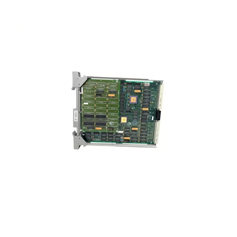
Honeywell 10005/1/1 Watchdog Module
Manufacturer: Honeywell
Product Number: 10005/1/1
Category: Watchdog Module / System Monitoring Module
System Platform: Honeywell Safety Manager
Function: Provides system monitoring and watchdog functionality
Application: System monitoring, fault detection, safety system supervision
Product Description
The 10005/1/1 watchdog module (WD) monitors system parameters including:
- the application loop maximum execution time in order to detect if the process is executing its program correctly and is not looping (hang-up).
- the application loop minimum execution time in order to detect if the processor is executing its program correctly and is not skipping program parts.
- 5 Vdc voltage monitoring for overvoltage and undervoltage (5 Vdc ± 5 %).
- memory error logic from CPU, COM and MEM modules. In case of a memory error, the watchdog output is de-energized.
- ESD input to de-energize the watchdog output independently from the processor. This ESD input is 24 Vdc and galvanically isolated from the internal 5 Vdc.
In order to be able to test the WD module for all functions, the WD module itself is a 2-out-of-3-voting system. Each section monitors the parameters described above.
The maximum WDG OUT output current is 900 mA (fuse 1A) 5 Vdc. If the number of output modules on the same 5 Vdc supply require a higher current (total of WD input currents of the output modules), then a watchdog repeater (WDR, 10302/1/1) must be used, and the load must be divided over the WD and the WDR.
Connections
For safety-relevant applications, the plant ESD can be connected directly to the WD module. In case of an ESD, the outputs will be de-energized independently from the processor.
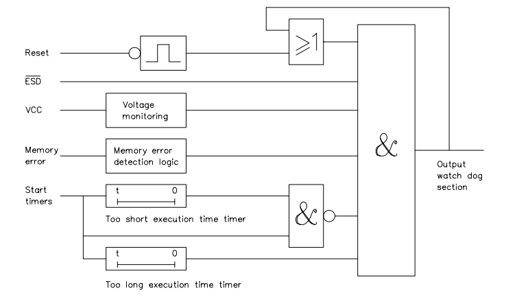
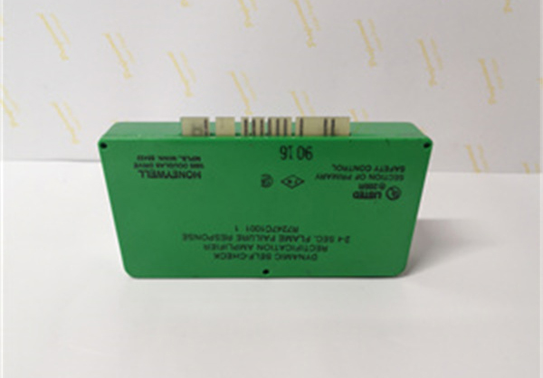
Figure 1 Watchdog section
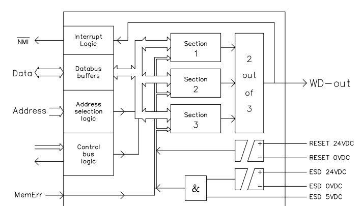
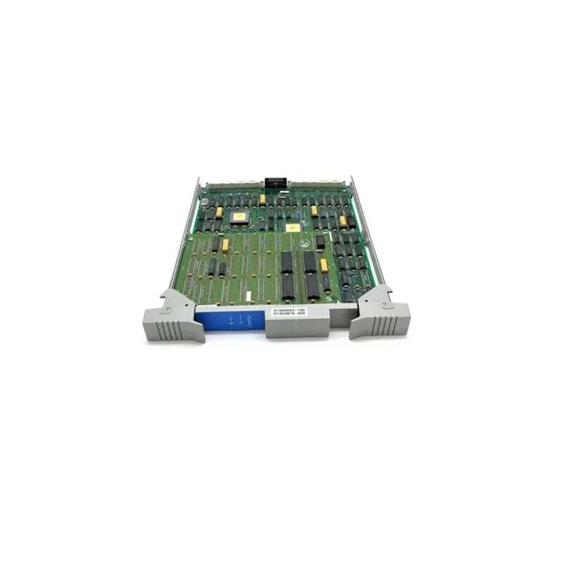
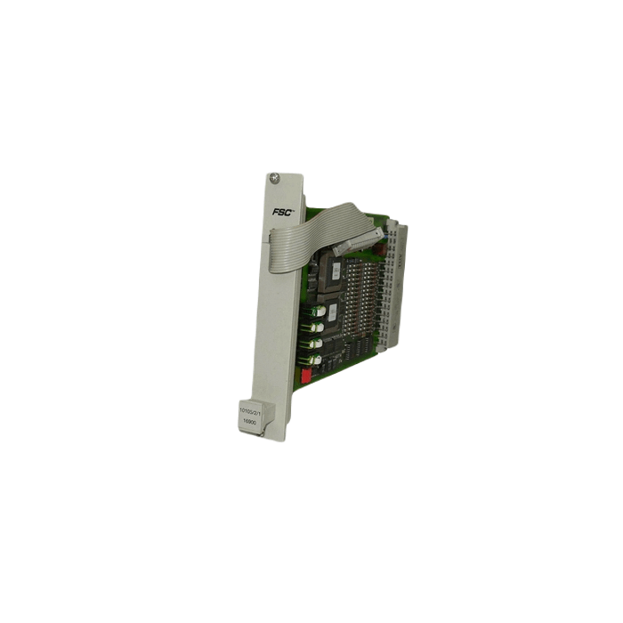
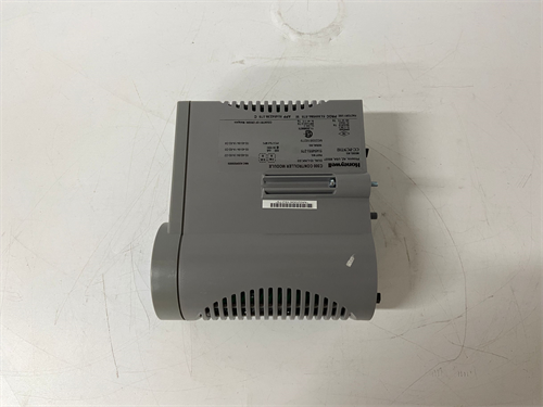
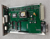
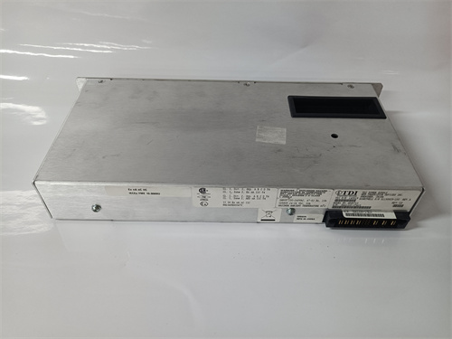
Figure 2 Watchdog module
The watchdog module terminates on the front to the 10005/O/1 module or the S-BUS located on top of the Central Part rack.
Jumpers
The jumper settings of the 10005/1/1 module are as follows:
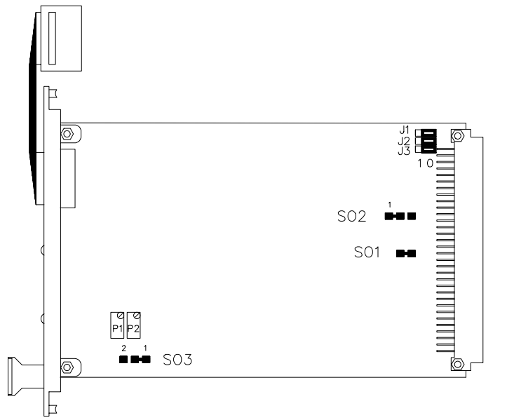
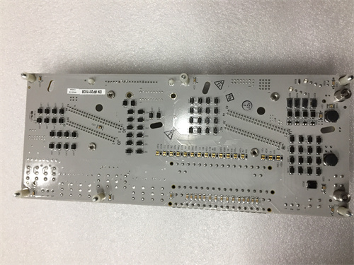
Figure 3 Jumper settings on 10005/1/1 module
The solder jumpers SO1 and SO2 are factory-set.
Position 1 (as shown in Figure 3) of the solder jumper SO3 is used for those applications that always require a manual start command.
The solder jumper SO3 in position 2 is used for those applications that have to start automatically after power-up (warm start). In the latter case, a manual reset is still required after a system trip. An automatic start is not executed if the system was powered off with a fault present (VDE 0116). In that case, it still requires a manual reset (resulting in a cold start).
Jumpers J1 to J3 must be positioned as shown in Figure 3.
Technical Data
The 10005/1/1 module has the following specifications:
General
- Type number: 10005/1/1 01301*
- Approvals: CE, TÜV, UL
- Software versions: all
- Space requirements: 4 TE, 3 HE (= 4 HP, 3U)
Power
- Power requirements: 5 Vdc 175 mA (without WDGOUT output current)
- Ripple content: < 50 mV p-p
Input
- ESD1 input: 24 Vdc 5 mA
- Reset input: 24 Vdc 10 mA
- ESD2 input: 5 Vdc 10 mA
*Note: 10005/1/1 modules with suffix code 01301 are functionally identical to 10005/1/1 modules without a suffix code. The changes involve improved production yield and reliability.
Note:
- Do not remove or replace this module while the power on its Central Part is on.
- While this information is presented in good faith and believed to be accurate, Honeywell Safety Management Systems B.V. disclaims the implied warranties of merchantability and fitness for a particular purpose and makes no express warranties except as may be stated in its written agreement with and for its customer.
- In no event is Honeywell Safety Management Systems B.V. liable to anyone for any indirect, special, or consequential damages.
- The information and specifications in this document are subject to change without notice.
 Loading comments...
Honeywell 10005/1/1 Watchdog Module
Manufacturer: Honeywell
Product Number: 10005/1/1
Category: Watchdog Module / System Monitoring Module
System Platform: Honeywell Safety Manager
Function: Provides system monitoring and watchdog functionality
Application: System monitoring, fault detection, safety system supervision
Product Description
The 10005/1/1 watchdog module (WD) monitors system parameters including:
- the application loop maximum execution time in order to detect if the process is executing its program correctly and is not looping (hang-up).
- the application loop minimum execution time in order to detect if the processor is executing its program correctly and is not skipping program parts.
- 5 Vdc voltage monitoring for overvoltage and undervoltage (5 Vdc ± 5 %).
- memory error logic from CPU, COM and MEM modules. In case of a memory error, the watchdog output is de-energized.
- ESD input to de-energize the watchdog output independently from the processor. This ESD input is 24 Vdc and galvanically isolated from the internal 5 Vdc.
In order to be able to test the WD module for all functions, the WD module itself is a 2-out-of-3-voting system. Each section monitors the parameters described above.
The maximum WDG OUT output current is 900 mA (fuse 1A) 5 Vdc. If the number of output modules on the same 5 Vdc supply require a higher current (total of WD input currents of the output modules), then a watchdog repeater (WDR, 10302/1/1) must be used, and the load must be divided over the WD and the WDR.
Connections
For safety-relevant applications, the plant ESD can be connected directly to the WD module. In case of an ESD, the outputs will be de-energized independently from the processor.
Figure 1 Watchdog section
Figure 2 Watchdog module
The watchdog module terminates on the front to the 10005/O/1 module or the S-BUS located on top of the Central Part rack.
Jumpers
The jumper settings of the 10005/1/1 module are as follows:
Figure 3 Jumper settings on 10005/1/1 module
The solder jumpers SO1 and SO2 are factory-set.
Position 1 (as shown in Figure 3) of the solder jumper SO3 is used for those applications that always require a manual start command.
The solder jumper SO3 in position 2 is used for those applications that have to start automatically after power-up (warm start). In the latter case, a manual reset is still required after a system trip. An automatic start is not executed if the system was powered off with a fault present (VDE 0116). In that case, it still requires a manual reset (resulting in a cold start).
Jumpers J1 to J3 must be positioned as shown in Figure 3.
Technical Data
The 10005/1/1 module has the following specifications:
General
- Type number: 10005/1/1 01301*
- Approvals: CE, TÜV, UL
- Software versions: all
- Space requirements: 4 TE, 3 HE (= 4 HP, 3U)
Power
- Power requirements: 5 Vdc 175 mA (without WDGOUT output current)
- Ripple content: < 50 mV p-p
Input
- ESD1 input: 24 Vdc 5 mA
- Reset input: 24 Vdc 10 mA
- ESD2 input: 5 Vdc 10 mA
*Note: 10005/1/1 modules with suffix code 01301 are functionally identical to 10005/1/1 modules without a suffix code. The changes involve improved production yield and reliability.
Note:
- Do not remove or replace this module while the power on its Central Part is on.
- While this information is presented in good faith and believed to be accurate, Honeywell Safety Management Systems B.V. disclaims the implied warranties of merchantability and fitness for a particular purpose and makes no express warranties except as may be stated in its written agreement with and for its customer.
- In no event is Honeywell Safety Management Systems B.V. liable to anyone for any indirect, special, or consequential damages.
- The information and specifications in this document are subject to change without notice.
Need a Custom Automation Solution?
Our team of experts can design and implement a tailored automation system to meet your specific requirements.