Our Products
Comprehensive industrial automation solutions for global industries
Contact us
If you are interested in our products and want to know more details,please Contact us,we will reply you as soon as we can.
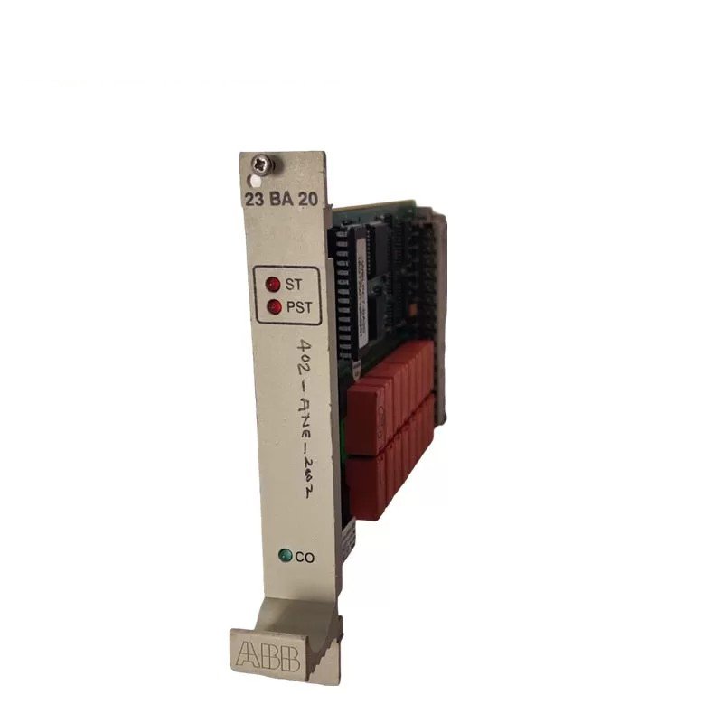
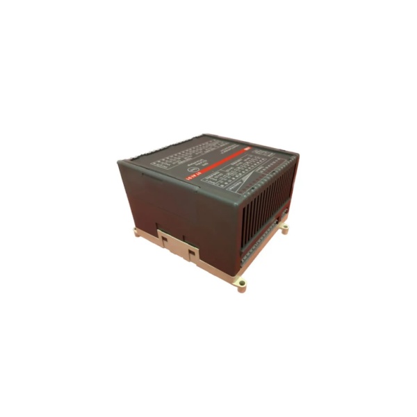
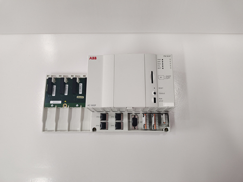
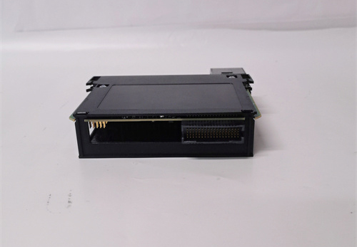
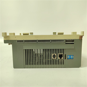
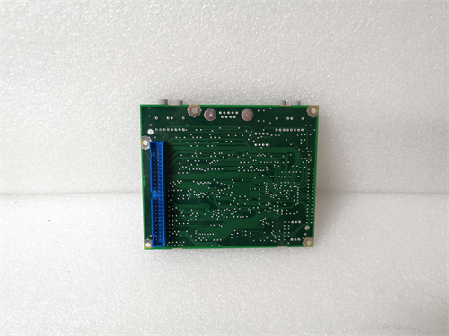
ABB 07AI91 GJR5251600R0202 Analog I/O Module
Product Description
ABB 07AI91 GJR5251600R0202 Analog I/O Module is used as a remote module at the CS31 system bus. It has 8 analog input channels with the following features:

The channels can be configured in pairs for the connection of the following temperature or voltage sensors:
± 10 V / ± 5 V / ± 500 mV / ± 50 mV
4...20 mA (with external 250 Ω resistor )
Pt100 / Pt1000 with linearization
Thermocouples types J, K and S with linearization
Only electrically isolated sensors may be used
The range of ± 5 V can also be used for measuring 0..20 mA with an additional external 250 Ω resistor.
The configuration of the input channels as well as the setting of the module address are performed with the DIL switches.
The 07 AI 91 uses one module address (group number) in the word input range. Each of the 8 channels use 16 bits. The unit is powered with 24 V DC. The CS31 system bus connection is electrically isolated from the rest of the unit. The module offers a number of diagnosis functions (see chapter "Diagnosis and displays"). The diagnosis functions perform a self-calibration for all channels.
Displays and operating elements on the front panel
8 green LEDs for channel selection and diagnosis, 8 green LEDs for analog value display of one channel
List of diagnosis information relating to the LEDs, when used for diagnosis display
Red LED for error messages
Test button
Configuration of input channels and setting of the module address at the CS31 bus
The measuring ranges for the analog channels are set in pairs (i.e. always for two channels together) using DIL switches 1 and 2. The setting of address DIL switch determines the module address, the analog value representation and the line frequency suppression (50 Hz, 60 Hz or none).
The switches are located under the slide cover on the right side of the module housing. The following figure shows the possible settings.
 Loading comments...
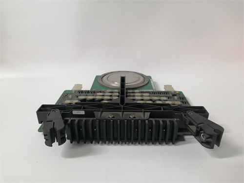
ABB 07AI91 GJR5251600R0202 Analog I/O Module
Product Description
ABB 07AI91 GJR5251600R0202 Analog I/O Module is used as a remote module at the CS31 system bus. It has 8 analog input channels with the following features:
The channels can be configured in pairs for the connection of the following temperature or voltage sensors:
± 10 V / ± 5 V / ± 500 mV / ± 50 mV
4...20 mA (with external 250 Ω resistor )
Pt100 / Pt1000 with linearization
Thermocouples types J, K and S with linearization
Only electrically isolated sensors may be used
The range of ± 5 V can also be used for measuring 0..20 mA with an additional external 250 Ω resistor.
The configuration of the input channels as well as the setting of the module address are performed with the DIL switches.
The 07 AI 91 uses one module address (group number) in the word input range. Each of the 8 channels use 16 bits. The unit is powered with 24 V DC. The CS31 system bus connection is electrically isolated from the rest of the unit. The module offers a number of diagnosis functions (see chapter "Diagnosis and displays"). The diagnosis functions perform a self-calibration for all channels.
Displays and operating elements on the front panel
8 green LEDs for channel selection and diagnosis, 8 green LEDs for analog value display of one channel
List of diagnosis information relating to the LEDs, when used for diagnosis display
Red LED for error messages
Test button
Configuration of input channels and setting of the module address at the CS31 bus
The measuring ranges for the analog channels are set in pairs (i.e. always for two channels together) using DIL switches 1 and 2. The setting of address DIL switch determines the module address, the analog value representation and the line frequency suppression (50 Hz, 60 Hz or none).
The switches are located under the slide cover on the right side of the module housing. The following figure shows the possible settings.
Need a Custom Automation Solution?
Our team of experts can design and implement a tailored automation system to meet your specific requirements.