Our Products
Comprehensive industrial automation solutions for global industries
Contact us
If you are interested in our products and want to know more details,please Contact us,we will reply you as soon as we can.
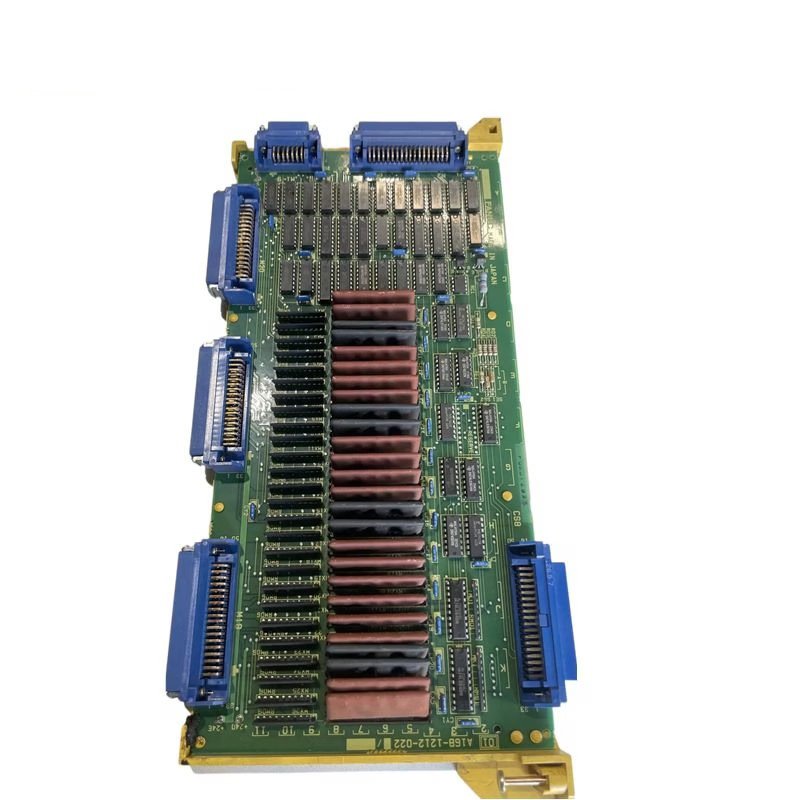


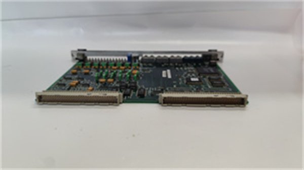
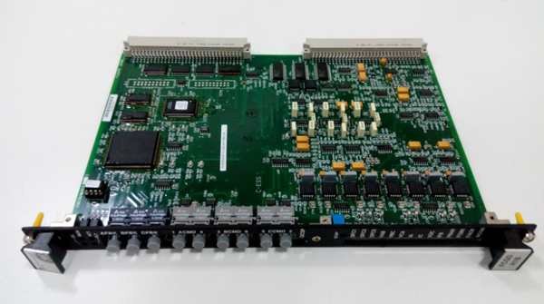
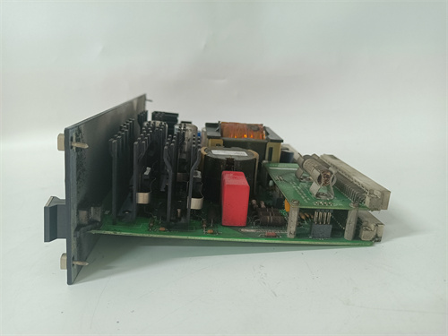
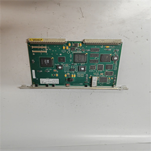
GE DS200IPCSG1A Insulated Gate Bipolar Transistor P3 Snubber Card
Manufacturer:General Electric
Product Number:GE DS200IPCSG1A
Payment Methods:T/T, PayPal, Western Union
Condition:New & In Stock
Warranty:1 Year
Lead Time:1-3 Working Days
Certificate:COO
Courier partners:DHL, UPS, TNT, FedEx and EMS.
Business hours:7*24
Product Description
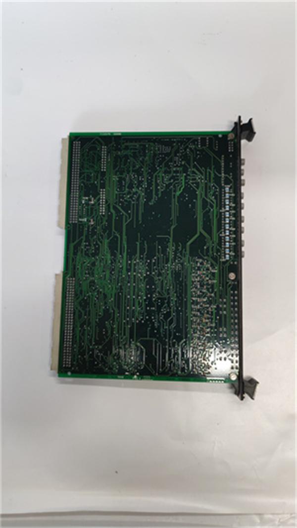
The GE DS200IPCSG1A is an Insulated Gate Bipolar Transistor (IGBT) P3 Snubber Card meticulously crafted by General Electric for applications within the drive control domain. This card plays a pivotal role in power electronics systems, especially those associated with the Mark V or EX2000 series.
IGBTs are widely used in high–power applications due to their ability to handle high voltages and currents. However, during the switching process, they generate voltage spikes and electromagnetic interference (EMI) which can be detrimental to the IGBT itself and other components in the circuit. The DS200IPCSG1A is engineered to mitigate these issues. It acts as a safeguard for IGBT modules by effectively absorbing and dissipating the energy of voltage spikes, thereby enhancing the overall reliability and lifespan of power electronic systems.
Detailed Parameter Table
| Parameter Name | Parameter Value |
| Product Model | GE DS200IPCSG1A |
| Manufacturer | General Electric (GE) |
| Product Category | Insulated Gate Bipolar Transistor (IGBT) P3 Snubber Card |
| Series | Drive Control |
| Power Requirements | +5V DC, 6A |
| Number of Relay Channels | 12 |
| Power Supply Voltage | 28V DC |
| Mounting | DIN–Rail Mounting |
| Technology | Surface Mount |
| Operating Temperature | -30°C to +65°C |
| Size | 15.9 cm (height) x 17.8 cm (width) |
| Country of Manufacturer | United States |
| Manual | GEH–6120 |
| Snubber Circuit | Present, designed to dampen voltage spikes during IGBT switching |
| Inductance | Low inductance to reduce electromagnetic interference (EMI) |
| Connector Type | Single 4–pin connector |
| Adjustment Screws | Six screws labeled C2E–1–A, C2E1–B, C2E–2–B, C2E–2–A, C1–A, and C1–B for hardware adjustments of connected IGBT models |
Core Advantages and Technical Highlights
Snubber Circuit for Voltage Spike Suppression
At the heart of the DS200IPCSG1A is its snubber circuit, a passive electronic circuit that is crucial for dampening the voltage spikes that occur when an IGBT switches on or off. The circuit consists of a precisely designed combination of capacitors and resistors. When a voltage spike is generated during IGBT switching, the capacitors in the snubber circuit quickly absorb the excess energy. The resistors then dissipate this energy in a controlled manner, preventing the voltage spike from reaching harmful levels. This not only protects the IGBT from potential damage due to over–voltage but also improves the overall performance of the power electronics system. By reducing voltage spikes, the IGBT can operate more efficiently, leading to increased system reliability and potentially lower maintenance costs.
Low Inductance Design for Reduced EMI
The DS200IPCSG1A features a low–inductance design, which is essential for minimizing the level of electromagnetic interference (EMI) generated by the IGBT during operation. In high–power applications, EMI can cause interference with other sensitive electronic components in the vicinity, leading to malfunctions or reduced performance. The low–inductance design of the snubber card helps to keep the current flow smooth and stable, reducing the generation of high–frequency electromagnetic fields. This is particularly important in applications where multiple electronic devices are operating in close proximity, such as in industrial control cabinets or complex power distribution systems. The reduced EMI ensures that the DS200IPCSG1A can co–exist with other components without causing interference issues, contributing to a more stable and reliable overall system.
Adjustable Hardware for IGBT Compatibility
The card is equipped with six adjustment screws labeled C2E–1–A, C2E1–B, C2E–2–B, C2E–2–A, C1–A, and C1–B. These screws enable users to make hardware adjustments to the connected IGBT models. This adjustability provides a high degree of flexibility, allowing the DS200IPCSG1A to be fine–tuned to work optimally with different IGBT modules. For example, in a motor drive application where different IGBTs may be used depending on the motor’s power requirements and operating conditions, the adjustment screws can be used to ensure that the snubber card provides the most effective protection for the specific IGBT in use. However, it is important to note that when making these adjustments using a screwdriver, caution must be exercised. Since there is voltage present in the drive and on the board, power should be turned off before any adjustments are made to avoid the risk of electrical shock or damage to the components.
Typical Application Scenarios
Motor Drives in Industrial Automation
In industrial automation settings, motor drives are used to control the speed and torque of electric motors. IGBTs are commonly employed in motor drives due to their high–power–handling capabilities. The GE DS200IPCSG1A finds extensive use in such applications. For instance, in a large–scale manufacturing plant where multiple conveyor belts are used to transport goods, the motor drives controlling these conveyor belts may utilize IGBTs. The DS200IPCSG1A is installed in the drive control system to protect the IGBTs from voltage spikes generated during the frequent starting and stopping of the motors. By ensuring the reliable operation of the IGBTs, the motor drives can function smoothly, minimizing downtime and ensuring the efficient flow of materials within the plant.
Renewable Energy Systems
Renewable energy systems, such as wind turbines and solar power inverters, also rely on IGBTs for power conversion. In a wind turbine, for example, the IGBTs are used to convert the variable–frequency, variable–voltage output of the generator into a stable, grid–compatible electrical signal. During this conversion process, voltage spikes can occur, which can be harmful to the IGBTs. The DS200IPCSG1A is integrated into the power electronics system of the wind turbine to suppress these voltage spikes. Its low–inductance design also helps in reducing EMI, which is crucial as wind turbines are often equipped with sensitive control and monitoring electronics. In solar power inverters, the DS200IPCSG1A serves a similar purpose, protecting the IGBTs and ensuring the efficient conversion of DC power from solar panels to AC power for grid connection.
Installation Preparation
Before installing the GE DS200IPCSG1A, it is essential to ensure that the power to the drive control system is completely turned off. This is a crucial safety measure to prevent the risk of electrical shock. The installation area should be clean and free from dust, moisture, and any other contaminants that could potentially affect the performance of the card. The required tools for installation include a suitable screwdriver for tightening and loosening the screws on the board and the DIN–rail mounting hardware. The DIN–rail on which the card will be mounted should be properly installed and securely fastened in the control cabinet. When handling the DS200IPCSG1A, it is recommended to use anti–static wrist straps to protect the sensitive electronic components on the card from electrostatic discharge.
 Loading comments...
GE DS200IPCSG1A Insulated Gate Bipolar Transistor P3 Snubber Card
Manufacturer:General Electric
Product Number:GE DS200IPCSG1A
Payment Methods:T/T, PayPal, Western Union
Condition:New & In Stock
Warranty:1 Year
Lead Time:1-3 Working Days
Certificate:COO
Courier partners:DHL, UPS, TNT, FedEx and EMS.
Business hours:7*24
Product Description
The GE DS200IPCSG1A is an Insulated Gate Bipolar Transistor (IGBT) P3 Snubber Card meticulously crafted by General Electric for applications within the drive control domain. This card plays a pivotal role in power electronics systems, especially those associated with the Mark V or EX2000 series.
IGBTs are widely used in high–power applications due to their ability to handle high voltages and currents. However, during the switching process, they generate voltage spikes and electromagnetic interference (EMI) which can be detrimental to the IGBT itself and other components in the circuit. The DS200IPCSG1A is engineered to mitigate these issues. It acts as a safeguard for IGBT modules by effectively absorbing and dissipating the energy of voltage spikes, thereby enhancing the overall reliability and lifespan of power electronic systems.
Detailed Parameter Table
| Parameter Name | Parameter Value |
| Product Model | GE DS200IPCSG1A |
| Manufacturer | General Electric (GE) |
| Product Category | Insulated Gate Bipolar Transistor (IGBT) P3 Snubber Card |
| Series | Drive Control |
| Power Requirements | +5V DC, 6A |
| Number of Relay Channels | 12 |
| Power Supply Voltage | 28V DC |
| Mounting | DIN–Rail Mounting |
| Technology | Surface Mount |
| Operating Temperature | -30°C to +65°C |
| Size | 15.9 cm (height) x 17.8 cm (width) |
| Country of Manufacturer | United States |
| Manual | GEH–6120 |
| Snubber Circuit | Present, designed to dampen voltage spikes during IGBT switching |
| Inductance | Low inductance to reduce electromagnetic interference (EMI) |
| Connector Type | Single 4–pin connector |
| Adjustment Screws | Six screws labeled C2E–1–A, C2E1–B, C2E–2–B, C2E–2–A, C1–A, and C1–B for hardware adjustments of connected IGBT models |
Core Advantages and Technical Highlights
Snubber Circuit for Voltage Spike Suppression
At the heart of the DS200IPCSG1A is its snubber circuit, a passive electronic circuit that is crucial for dampening the voltage spikes that occur when an IGBT switches on or off. The circuit consists of a precisely designed combination of capacitors and resistors. When a voltage spike is generated during IGBT switching, the capacitors in the snubber circuit quickly absorb the excess energy. The resistors then dissipate this energy in a controlled manner, preventing the voltage spike from reaching harmful levels. This not only protects the IGBT from potential damage due to over–voltage but also improves the overall performance of the power electronics system. By reducing voltage spikes, the IGBT can operate more efficiently, leading to increased system reliability and potentially lower maintenance costs.
Low Inductance Design for Reduced EMI
The DS200IPCSG1A features a low–inductance design, which is essential for minimizing the level of electromagnetic interference (EMI) generated by the IGBT during operation. In high–power applications, EMI can cause interference with other sensitive electronic components in the vicinity, leading to malfunctions or reduced performance. The low–inductance design of the snubber card helps to keep the current flow smooth and stable, reducing the generation of high–frequency electromagnetic fields. This is particularly important in applications where multiple electronic devices are operating in close proximity, such as in industrial control cabinets or complex power distribution systems. The reduced EMI ensures that the DS200IPCSG1A can co–exist with other components without causing interference issues, contributing to a more stable and reliable overall system.
Adjustable Hardware for IGBT Compatibility
The card is equipped with six adjustment screws labeled C2E–1–A, C2E1–B, C2E–2–B, C2E–2–A, C1–A, and C1–B. These screws enable users to make hardware adjustments to the connected IGBT models. This adjustability provides a high degree of flexibility, allowing the DS200IPCSG1A to be fine–tuned to work optimally with different IGBT modules. For example, in a motor drive application where different IGBTs may be used depending on the motor’s power requirements and operating conditions, the adjustment screws can be used to ensure that the snubber card provides the most effective protection for the specific IGBT in use. However, it is important to note that when making these adjustments using a screwdriver, caution must be exercised. Since there is voltage present in the drive and on the board, power should be turned off before any adjustments are made to avoid the risk of electrical shock or damage to the components.
Typical Application Scenarios
Motor Drives in Industrial Automation
In industrial automation settings, motor drives are used to control the speed and torque of electric motors. IGBTs are commonly employed in motor drives due to their high–power–handling capabilities. The GE DS200IPCSG1A finds extensive use in such applications. For instance, in a large–scale manufacturing plant where multiple conveyor belts are used to transport goods, the motor drives controlling these conveyor belts may utilize IGBTs. The DS200IPCSG1A is installed in the drive control system to protect the IGBTs from voltage spikes generated during the frequent starting and stopping of the motors. By ensuring the reliable operation of the IGBTs, the motor drives can function smoothly, minimizing downtime and ensuring the efficient flow of materials within the plant.
Renewable Energy Systems
Renewable energy systems, such as wind turbines and solar power inverters, also rely on IGBTs for power conversion. In a wind turbine, for example, the IGBTs are used to convert the variable–frequency, variable–voltage output of the generator into a stable, grid–compatible electrical signal. During this conversion process, voltage spikes can occur, which can be harmful to the IGBTs. The DS200IPCSG1A is integrated into the power electronics system of the wind turbine to suppress these voltage spikes. Its low–inductance design also helps in reducing EMI, which is crucial as wind turbines are often equipped with sensitive control and monitoring electronics. In solar power inverters, the DS200IPCSG1A serves a similar purpose, protecting the IGBTs and ensuring the efficient conversion of DC power from solar panels to AC power for grid connection.
Installation Preparation
Before installing the GE DS200IPCSG1A, it is essential to ensure that the power to the drive control system is completely turned off. This is a crucial safety measure to prevent the risk of electrical shock. The installation area should be clean and free from dust, moisture, and any other contaminants that could potentially affect the performance of the card. The required tools for installation include a suitable screwdriver for tightening and loosening the screws on the board and the DIN–rail mounting hardware. The DIN–rail on which the card will be mounted should be properly installed and securely fastened in the control cabinet. When handling the DS200IPCSG1A, it is recommended to use anti–static wrist straps to protect the sensitive electronic components on the card from electrostatic discharge.
Need a Custom Automation Solution?
Our team of experts can design and implement a tailored automation system to meet your specific requirements.