Our Products
Comprehensive industrial automation solutions for global industries
Contact us
If you are interested in our products and want to know more details,please Contact us,we will reply you as soon as we can.
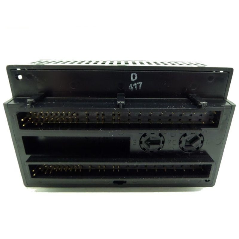
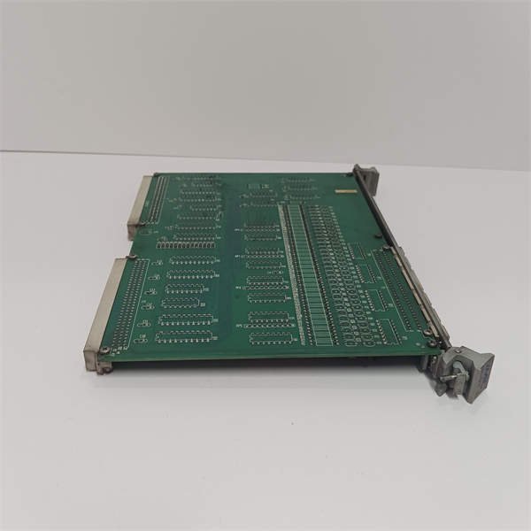
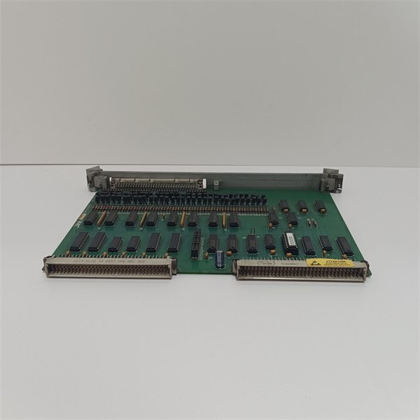
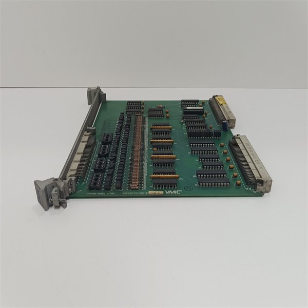
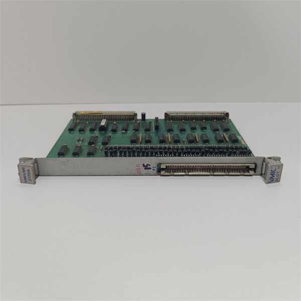
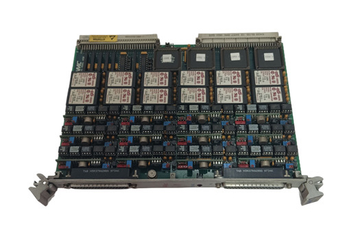
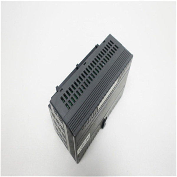
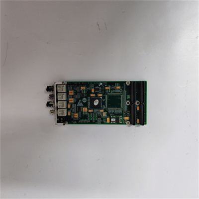
General Electric VMIVME-2170A 32–Bit Optically Coupled Digital Output Board
Manufacturer: General Electric
Product Number: VMIVME-2170A
Category: 32-Bit Optically Coupled Digital Output Board
Number of Channels: 32
Output Type: Optically coupled digital outputs
Architecture: VMEbus
Function: Critical link between control systems and external devices in industrial setups
Isolation: Optical isolation for reliable and isolated control
Product Description
The GE VMIVME – 2170A is a 32 – bit optically coupled digital output board meticulously engineered for the VMEbus architecture. It serves as a crucial link between control systems and external devices in industrial setups, offering a reliable and efficient means of translating digital signals into actionable outputs.
This board builds on GE’s reputation for quality and innovation in industrial automation. By leveraging optical isolation technology, it provides high – level protection against electrical noise and interference, ensuring stable and accurate operation even in electrically noisy environments. Its design caters to a wide range of applications where precise control of external loads is essential, making it a staple in many industrial control systems.
Detailed Parameter Table
| Parameter name | Parameter value |
| Product model | VMIVME – 2170A |
| Manufacturer | GE (General Electric) |
| Product category | 32 – Bit Optically Coupled Digital Output Board |
| Output channels | 32 |
| Output current per channel | Up to 2 amps |
| Output voltage range | Maximum 30V |
| Input voltage | 5V DC |
| Input current per channel | 10 mA |
| Isolation voltage | Sustained: 1 kV; Pulsed: 6 kV (some sources state 2500 VDC for isolation voltage in different test conditions) |
| Data transfer types | 8 – bit (D8) or 16 – bit (D16) |
| Access time | Maximum 250 ns |
| Data polarity | Positive true or negative true |
| Output characteristics | Open drain |
| Form factor | Double eurocard with front panel, compatible with VMEbus |
| Operating temperature range | – 40 °C to 85 °C |
| Storage temperature range | – 55 °C to 125 °C |
| Humidity | 5% – 95% RH (non – condensing) |
| Dimensions | Approximately 6.8″ x 4.3″ x 1.0″ |
| Weight | Approximately 380 g (10 ounces) |
| Warranty | 12 months |
Core Advantages and Technical Highlights
Optical isolation for enhanced reliability: The use of optical coupling in the VMIVME – 2170A provides a high degree of isolation between the input and output sides. With a sustained isolation voltage of 1 kV and a pulsed isolation voltage of 6 kV (or 2500 VDC as per some specifications), it can effectively protect connected devices from electrical transients and surges. This isolation not only safeguards the board itself but also the equipment it controls, reducing the risk of damage due to electrical malfunctions.
High – current output capabilities: Each of the 32 output channels on the VMIVME – 2170A can drive up to 2 amps of current. This high – current capacity makes it suitable for powering a variety of external loads, such as relays, solenoids, and small motors. In industrial control applications, this means the board can directly interface with and control actuators without the need for additional power amplification stages in many cases, simplifying the system design.
Short – circuit and overload protection: To further enhance its reliability, the VMIVME – 2170A is equipped with built – in short – circuit and overload protection mechanisms. In the event of a short – circuit or excessive current draw on an output channel, the protection circuitry activates to prevent damage to the board and the connected devices. This feature is crucial for maintaining the integrity of the control system, especially in industrial environments where unexpected electrical faults can occur.
Flexible data transfer and compatibility: The board supports both 8 – bit and 16 – bit data transfers, allowing for greater flexibility in interfacing with different types of control systems. Its compatibility with the VMEbus standard ensures seamless integration into existing VME – based industrial control systems. This makes it an ideal choice for retrofitting projects, as well as for new system designs where compatibility and ease of integration are key considerations.
Typical Application Scenarios
Industrial control systems: In manufacturing plants, the VMIVME – 2170A can be used to control conveyor belts, robotic arms, and other automated machinery. For example, it can receive digital commands from a programmable logic controller (PLC) and then drive the relays or solenoids that operate the motors and actuators of these devices. The board’s high – current output capabilities and short – circuit protection are well – suited for the demanding electrical requirements of industrial machinery.
Test and measurement equipment: In test and measurement applications, the VMIVME – 2170A can be used to control the switching of test signals and the activation of load banks. For instance, in a power electronics testing facility, it can be used to control the connection and disconnection of different resistive or inductive loads to simulate real – world operating conditions for power supplies or other electrical components. The board’s optical isolation helps to prevent any interference from the test equipment’s electrical signals, ensuring accurate measurement results.
Data acquisition systems: In data acquisition setups, the VMIVME – 2170A can be used to control the activation and deactivation of sensors or data loggers. For example, in a large – scale environmental monitoring project, it can be used to turn on and off various sensors at specific intervals, ensuring that data is collected at the right times. The board’s compatibility with different data transfer modes allows for easy integration with data acquisition software and hardware.
Installation Commissioning and Maintenance Instructions
Installation preparation: Before installing the VMIVME – 2170A, ensure that the VMEbus backplane in which it will be installed is properly powered off. Use anti – static wristbands and other static – control measures to prevent electrostatic discharge (ESD) damage to the board. Check that the physical dimensions of the installation location are compatible with the board’s form factor. Verify that the input voltage requirements (5V DC) are met by the power supply in the system.
Commissioning: Once installed, power on the system. Use the appropriate software or control interface to configure the data transfer mode (8 – bit or 16 – bit) according to the requirements of the connected control system. Test each output channel by sending digital signals and verifying that the connected external devices respond as expected. Measure the output current and voltage on each channel using appropriate test equipment to ensure they are within the specified ranges. Check for any signs of overheating or abnormal operation during the initial testing phase.
Maintenance suggestions: Regularly perform visual inspections of the VMIVME – 2170A for any signs of physical damage, such as bent pins or discolored components. Check for loose connections on the board and in the VMEbus backplane. Monitor the operating temperature of the board, especially in high – temperature environments, to ensure it remains within the specified range. If any output channels fail to operate correctly, use diagnostic tools to check for short – circuits, open – circuits, or other electrical faults. Replace the board if any irreparable damage is detected.
 Loading comments...
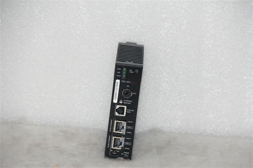
General Electric VMIVME-2170A 32–Bit Optically Coupled Digital Output Board
Manufacturer: General Electric
Product Number: VMIVME-2170A
Category: 32-Bit Optically Coupled Digital Output Board
Number of Channels: 32
Output Type: Optically coupled digital outputs
Architecture: VMEbus
Function: Critical link between control systems and external devices in industrial setups
Isolation: Optical isolation for reliable and isolated control
Product Description
The GE VMIVME – 2170A is a 32 – bit optically coupled digital output board meticulously engineered for the VMEbus architecture. It serves as a crucial link between control systems and external devices in industrial setups, offering a reliable and efficient means of translating digital signals into actionable outputs.
This board builds on GE’s reputation for quality and innovation in industrial automation. By leveraging optical isolation technology, it provides high – level protection against electrical noise and interference, ensuring stable and accurate operation even in electrically noisy environments. Its design caters to a wide range of applications where precise control of external loads is essential, making it a staple in many industrial control systems.
Detailed Parameter Table
| Parameter name | Parameter value |
| Product model | VMIVME – 2170A |
| Manufacturer | GE (General Electric) |
| Product category | 32 – Bit Optically Coupled Digital Output Board |
| Output channels | 32 |
| Output current per channel | Up to 2 amps |
| Output voltage range | Maximum 30V |
| Input voltage | 5V DC |
| Input current per channel | 10 mA |
| Isolation voltage | Sustained: 1 kV; Pulsed: 6 kV (some sources state 2500 VDC for isolation voltage in different test conditions) |
| Data transfer types | 8 – bit (D8) or 16 – bit (D16) |
| Access time | Maximum 250 ns |
| Data polarity | Positive true or negative true |
| Output characteristics | Open drain |
| Form factor | Double eurocard with front panel, compatible with VMEbus |
| Operating temperature range | – 40 °C to 85 °C |
| Storage temperature range | – 55 °C to 125 °C |
| Humidity | 5% – 95% RH (non – condensing) |
| Dimensions | Approximately 6.8″ x 4.3″ x 1.0″ |
| Weight | Approximately 380 g (10 ounces) |
| Warranty | 12 months |
Core Advantages and Technical Highlights
Optical isolation for enhanced reliability: The use of optical coupling in the VMIVME – 2170A provides a high degree of isolation between the input and output sides. With a sustained isolation voltage of 1 kV and a pulsed isolation voltage of 6 kV (or 2500 VDC as per some specifications), it can effectively protect connected devices from electrical transients and surges. This isolation not only safeguards the board itself but also the equipment it controls, reducing the risk of damage due to electrical malfunctions.
High – current output capabilities: Each of the 32 output channels on the VMIVME – 2170A can drive up to 2 amps of current. This high – current capacity makes it suitable for powering a variety of external loads, such as relays, solenoids, and small motors. In industrial control applications, this means the board can directly interface with and control actuators without the need for additional power amplification stages in many cases, simplifying the system design.
Short – circuit and overload protection: To further enhance its reliability, the VMIVME – 2170A is equipped with built – in short – circuit and overload protection mechanisms. In the event of a short – circuit or excessive current draw on an output channel, the protection circuitry activates to prevent damage to the board and the connected devices. This feature is crucial for maintaining the integrity of the control system, especially in industrial environments where unexpected electrical faults can occur.
Flexible data transfer and compatibility: The board supports both 8 – bit and 16 – bit data transfers, allowing for greater flexibility in interfacing with different types of control systems. Its compatibility with the VMEbus standard ensures seamless integration into existing VME – based industrial control systems. This makes it an ideal choice for retrofitting projects, as well as for new system designs where compatibility and ease of integration are key considerations.
Typical Application Scenarios
Industrial control systems: In manufacturing plants, the VMIVME – 2170A can be used to control conveyor belts, robotic arms, and other automated machinery. For example, it can receive digital commands from a programmable logic controller (PLC) and then drive the relays or solenoids that operate the motors and actuators of these devices. The board’s high – current output capabilities and short – circuit protection are well – suited for the demanding electrical requirements of industrial machinery.
Test and measurement equipment: In test and measurement applications, the VMIVME – 2170A can be used to control the switching of test signals and the activation of load banks. For instance, in a power electronics testing facility, it can be used to control the connection and disconnection of different resistive or inductive loads to simulate real – world operating conditions for power supplies or other electrical components. The board’s optical isolation helps to prevent any interference from the test equipment’s electrical signals, ensuring accurate measurement results.
Data acquisition systems: In data acquisition setups, the VMIVME – 2170A can be used to control the activation and deactivation of sensors or data loggers. For example, in a large – scale environmental monitoring project, it can be used to turn on and off various sensors at specific intervals, ensuring that data is collected at the right times. The board’s compatibility with different data transfer modes allows for easy integration with data acquisition software and hardware.
Installation Commissioning and Maintenance Instructions
Installation preparation: Before installing the VMIVME – 2170A, ensure that the VMEbus backplane in which it will be installed is properly powered off. Use anti – static wristbands and other static – control measures to prevent electrostatic discharge (ESD) damage to the board. Check that the physical dimensions of the installation location are compatible with the board’s form factor. Verify that the input voltage requirements (5V DC) are met by the power supply in the system.
Commissioning: Once installed, power on the system. Use the appropriate software or control interface to configure the data transfer mode (8 – bit or 16 – bit) according to the requirements of the connected control system. Test each output channel by sending digital signals and verifying that the connected external devices respond as expected. Measure the output current and voltage on each channel using appropriate test equipment to ensure they are within the specified ranges. Check for any signs of overheating or abnormal operation during the initial testing phase.
Maintenance suggestions: Regularly perform visual inspections of the VMIVME – 2170A for any signs of physical damage, such as bent pins or discolored components. Check for loose connections on the board and in the VMEbus backplane. Monitor the operating temperature of the board, especially in high – temperature environments, to ensure it remains within the specified range. If any output channels fail to operate correctly, use diagnostic tools to check for short – circuits, open – circuits, or other electrical faults. Replace the board if any irreparable damage is detected.
Need a Custom Automation Solution?
Our team of experts can design and implement a tailored automation system to meet your specific requirements.