Our Products
Comprehensive industrial automation solutions for global industries
Contact us
If you are interested in our products and want to know more details,please Contact us,we will reply you as soon as we can.
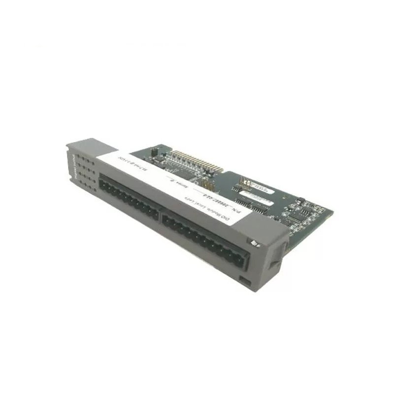
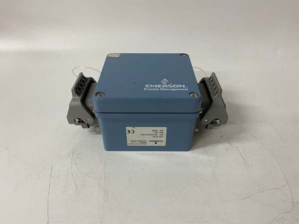
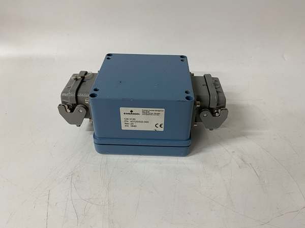
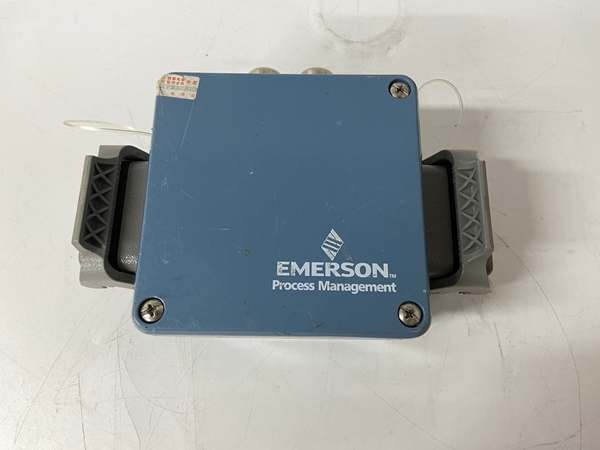
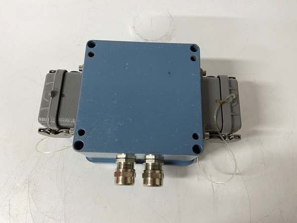
Emerson A3120 022-000 CSI3120 Vibration Monitor
Manufacturer: Emerson
Product Number: A3120 (022-000)
Category: CSI3120 Vibration Monitor
Processor: 32-bit floating-point
Number of Channels: 4
Frequency Range: 0.5 Hz to 40 kHz
Dynamic Range: >120 dB
Input Signal Types: Accelerometer, velocity, displacement
Operating Temperature: -20°C to +50°C
Power Supply: 24 V DC
Product Description
The A3120 is built around a 32-bit floating-point processor with four dedicated signal conditioners—one per channel. It’s not just a “reader”; it’s an intelligent analyzer. Here’s how it works: the piezoelectric accelerometer converts mechanical vibration into a tiny electrical signal (millivolts). The signal conditioner amplifies that signal and filters out electrical noise (like from VFDs). The processor then converts the raw signal into usable units—velocity (mm/s) or displacement (μm)—and runs an FFT algorithm to break the vibration into frequency components.
Key Technical Specifications
-
Model Number: A3120 (CSI3120)
-
Manufacturer: Emerson Automation Solutions
-
Measurement Input: Piezoelectric accelerometer (100mV/g typical)
-
Measurement Range: Velocity: 0.1-100 mm/s RMS; Displacement: 0.1-1000 μm peak-peak
-
Protocol Support: Modbus TCP/RTU, Ethernet/IP, OPC UA, HART v7
-
Channel Capacity: 4 independent channels (expandable to 16 via daisy-chain)
-
Operating Temperature: -20°C to 65°C (-4°F to 149°F)
-
Power Supply: 24V DC ±20% or 100-240V AC ±10%, 30W max
-
Isolation: 1500V rms (channel to ground)
-
Environmental Rating: IP65/NEMA 4X (indoor); IP67/NEMA 4X (outdoor 316L)
-
Certifications: SIL 2 (IEC 61508), ATEX Zone 2, IECEx, UL, CSA
-
Response Time: <100ms for alarm triggers
-
Measurement Technology: Piezoelectric accelerometer input, supporting velocity (mm/s RMS) and displacement (μm peak-peak) conversion, FFT spectral analysis range 0.1Hz-10kHz
-
Measurement Accuracy: ±0.1% full scale for vibration; ±0.5°C for temperature (when equipped with temperature sensor)
-
Measurement Range: Vibration velocity 0.1-100 mm/s RMS; displacement 0.1-1000 μm peak-peak; temperature -40°C to 120°C
-
Channel Capacity: 4 independent channels, expandable to 16 channels via daisy-chain connection, simultaneous sampling per channel
-
Communication Protocols: Modbus TCP/RTU, Ethernet/IP, OPC UA, HART v7; 4-20mA analog output available for each channel
-
Power Supply: Dual redundant inputs, supporting 24V DC ±20% or 100-240V AC ±10%, maximum power consumption 30W
-
Environmental Protection: Indoor model (powder-coated steel housing) IP65/NEMA 4X; outdoor model (316L stainless steel) IP67/NEMA 4X
-
Operating Temperature: -20°C to 65°C (-4°F to 149°F); storage temperature -40°C to 85°C (-40°F to 185°F)
-
Compliance & Certifications: SIL 2 (IEC 61508), IEC 61511, ATEX Zone 2, IECEx Zone 2, UL, CSA, CE, FM Approved
Field Application & Problem Solved
In the field, the single biggest cost driver for rotating equipment is unplanned downtime. I’ve seen a single centrifugal compressor failure shut down a refinery’s diesel unit for 14 hours—$1.2 million in lost production. The old way? Monthly manual vibration checks with a handheld analyzer. These miss transient faults—like a bearing starting to flake—and give you a snapshot, not a trend. This monitor solves that by staying on 24/7, turning reactive “break-fix” maintenance into proactive repairs.
You’ll find these installed where equipment failure hurts most: refinery hydrocrackers, gas plant reciprocating compressors, and power plant steam turbines. At a Texas petrochemical site last year, we put 12 of these on their reactor feed pumps. Within three months, one unit flagged a 12% vibration increase at 2x the pump’s running speed—classic misalignment. We fixed it during a scheduled shift change, no downtime. Six months later, their pump maintenance costs were down 32%.
Its core value is precision and timing. It doesn’t just scream “alarm”—it tells you what’s wrong (bearing, unbalance, misalignment) and how bad it is. For maintenance teams, that means no more guessing if a pump needs to be pulled immediately or can run until the next outage. It turns vibration data into actionable decisions, which is worth its weight in downtime savings.
In industrial production, rotating equipment (pumps, motors, compressors, turbines) is the core of the production line, and its unexpected failure often leads to huge economic losses. The Emerson A3120 022-000 CSI3120 vibration monitor solves the pain points of traditional maintenance methods through 24/7 online real-time monitoring, and its core application value is mainly reflected in three aspects:
-
Predictive Maintenance Implementation: The monitor can detect early fault signs such as bearing wear, rotor unbalance, and shaft misalignment 2-3 weeks in advance by continuously tracking vibration and temperature data. It triggers early warnings before equipment failure, helping enterprises convert “break-fix” reactive maintenance into scheduled proactive maintenance.
-
Downtime and Cost Reduction: According to industrial data statistics, the application of this monitor can reduce unplanned downtime of rotating equipment by 30-40%, and reduce maintenance costs by 20-30%. For example, a petrochemical plant in Texas reduced the downtime of centrifugal compressors by 35% within half a year after installing the CSI3120, saving maintenance costs of $800,000.
-
Safety and Compliance Guarantee: With SIL 2 certification, the monitor meets the safety integrity requirements of critical process links (such as power plant steam turbines, refinery hydrocrackers). It not only ensures the stable operation of equipment but also helps enterprises comply with IEC 61511, ANSI/ISA-101.01 and other industry standards.
Sensor Mounting: Stop Putting Them on Motor Frames
Rookies mount accelerometers on the motor’s outer shell—big mistake. The motor frame dampens vibration, so you’ll miss bearing faults until it’s too late. I saw this at a paper mill: the monitor showed “normal” vibes, but the pump bearing seized two days later. Mount the sensor directly on the bearing housing, within 2 inches of the bearing, using epoxy (permanent) or a magnetic mount (temporary). For large turbines, use two sensors per bearing (90° apart) to catch axial and radial movement.
Calibration: Don’t Skip the Shaker Table
Generic accelerometers or uncalibrated sensors make the monitor useless. Last quarter, a gas plant used $200 off-brand sensors—their readings were 18% low. Always use Emerson’s 022-003 accelerometer (100mV/g) and calibrate with a shaker table after install. Apply a 10 mm/s RMS test signal—if the monitor reads outside 9.9-10.1 mm/s, replace the sensor or signal card.
Data Analysis: FFT is Your Friend, Not a Bonus
Most teams only watch the “overall vibration” number. That’s like checking your car’s speedometer but ignoring the check engine light. The FFT spectrum tells you why it’s vibrating. A peak at 1x speed = unbalance; 2x = misalignment; peaks matching the bearing’s fault frequency = worn rollers. Set the monitor to auto-save FFT data on alarms—when the alert goes off, you’ll have the proof you need to diagnose fast.
Sensor Matching and Calibration
The accuracy of vibration measurement depends on the matching degree of accelerometers. It is strictly forbidden to use non-Emerson certified accelerometers. The recommended matching model is 022-003 (100mV/g sensitivity). After installation, calibration must be carried out with a standard shaker table: apply a known 10 mm/s vibration signal, and the monitor reading error should be within ±0.1 mm/s. If the error exceeds 1%, the sensor or signal conditioning module should be checked and replaced.
Correct Sensor Installation
Sensor installation location and method directly affect monitoring effectiveness. The “direct mounting principle” must be followed: install the accelerometer on the bearing housing (radial and axial directions) within 5cm of the bearing, using epoxy bonding or magnetic mounting. For large turbines, two sensors should be installed per bearing (90° apart) to capture full-direction vibration. After installation, perform a “hammer test”: tap the bearing housing, and the monitor should immediately record a vibration spike; if there is no response, the mounting location needs to be adjusted.
Data Analysis and Fault Diagnosis
Avoid only focusing on overall vibration values and ignoring FFT spectral analysis. Use Emerson AMS Machinery Health Manager software to interpret spectral data: peaks at 1× equipment running speed indicate rotor unbalance; peaks at 2× speed indicate shaft misalignment; peaks matching bearing fault frequencies indicate worn bearings. Set the monitor to automatically capture FFT spectra when an alarm is triggered, which can save fault moment data and provide a basis for root cause analysis.
Daily Maintenance and Inspection
-
Daily: Check the monitor’s power supply status, indicator lights (normal operation: green; alarm: red; fault: yellow) and communication connection.
-
Weekly: Use HART communicator to check sensor signal strength and diagnostic data, focusing on “sensor degradation” and “signal drift” alerts.
-
Monthly: Clean the monitor housing and sensor surface; verify the accuracy of 4-20mA analog output with a multimeter; back up historical vibration data.
-
Quarterly: Perform a full-system calibration, including sensor sensitivity and monitor measurement accuracy.
 Loading comments...
Emerson A3120 022-000 CSI3120 Vibration Monitor
Manufacturer: Emerson
Product Number: A3120 (022-000)
Category: CSI3120 Vibration Monitor
Processor: 32-bit floating-point
Number of Channels: 4
Frequency Range: 0.5 Hz to 40 kHz
Dynamic Range: >120 dB
Input Signal Types: Accelerometer, velocity, displacement
Operating Temperature: -20°C to +50°C
Power Supply: 24 V DC
Product Description
The A3120 is built around a 32-bit floating-point processor with four dedicated signal conditioners—one per channel. It’s not just a “reader”; it’s an intelligent analyzer. Here’s how it works: the piezoelectric accelerometer converts mechanical vibration into a tiny electrical signal (millivolts). The signal conditioner amplifies that signal and filters out electrical noise (like from VFDs). The processor then converts the raw signal into usable units—velocity (mm/s) or displacement (μm)—and runs an FFT algorithm to break the vibration into frequency components.
Key Technical Specifications
-
Model Number: A3120 (CSI3120)
-
Manufacturer: Emerson Automation Solutions
-
Measurement Input: Piezoelectric accelerometer (100mV/g typical)
-
Measurement Range: Velocity: 0.1-100 mm/s RMS; Displacement: 0.1-1000 μm peak-peak
-
Protocol Support: Modbus TCP/RTU, Ethernet/IP, OPC UA, HART v7
-
Channel Capacity: 4 independent channels (expandable to 16 via daisy-chain)
-
Operating Temperature: -20°C to 65°C (-4°F to 149°F)
-
Power Supply: 24V DC ±20% or 100-240V AC ±10%, 30W max
-
Isolation: 1500V rms (channel to ground)
-
Environmental Rating: IP65/NEMA 4X (indoor); IP67/NEMA 4X (outdoor 316L)
-
Certifications: SIL 2 (IEC 61508), ATEX Zone 2, IECEx, UL, CSA
-
Response Time: <100ms for alarm triggers
-
Measurement Technology: Piezoelectric accelerometer input, supporting velocity (mm/s RMS) and displacement (μm peak-peak) conversion, FFT spectral analysis range 0.1Hz-10kHz
-
Measurement Accuracy: ±0.1% full scale for vibration; ±0.5°C for temperature (when equipped with temperature sensor)
-
Measurement Range: Vibration velocity 0.1-100 mm/s RMS; displacement 0.1-1000 μm peak-peak; temperature -40°C to 120°C
-
Channel Capacity: 4 independent channels, expandable to 16 channels via daisy-chain connection, simultaneous sampling per channel
-
Communication Protocols: Modbus TCP/RTU, Ethernet/IP, OPC UA, HART v7; 4-20mA analog output available for each channel
-
Power Supply: Dual redundant inputs, supporting 24V DC ±20% or 100-240V AC ±10%, maximum power consumption 30W
-
Environmental Protection: Indoor model (powder-coated steel housing) IP65/NEMA 4X; outdoor model (316L stainless steel) IP67/NEMA 4X
-
Operating Temperature: -20°C to 65°C (-4°F to 149°F); storage temperature -40°C to 85°C (-40°F to 185°F)
-
Compliance & Certifications: SIL 2 (IEC 61508), IEC 61511, ATEX Zone 2, IECEx Zone 2, UL, CSA, CE, FM Approved
Field Application & Problem Solved
In the field, the single biggest cost driver for rotating equipment is unplanned downtime. I’ve seen a single centrifugal compressor failure shut down a refinery’s diesel unit for 14 hours—$1.2 million in lost production. The old way? Monthly manual vibration checks with a handheld analyzer. These miss transient faults—like a bearing starting to flake—and give you a snapshot, not a trend. This monitor solves that by staying on 24/7, turning reactive “break-fix” maintenance into proactive repairs.
You’ll find these installed where equipment failure hurts most: refinery hydrocrackers, gas plant reciprocating compressors, and power plant steam turbines. At a Texas petrochemical site last year, we put 12 of these on their reactor feed pumps. Within three months, one unit flagged a 12% vibration increase at 2x the pump’s running speed—classic misalignment. We fixed it during a scheduled shift change, no downtime. Six months later, their pump maintenance costs were down 32%.
Its core value is precision and timing. It doesn’t just scream “alarm”—it tells you what’s wrong (bearing, unbalance, misalignment) and how bad it is. For maintenance teams, that means no more guessing if a pump needs to be pulled immediately or can run until the next outage. It turns vibration data into actionable decisions, which is worth its weight in downtime savings.
In industrial production, rotating equipment (pumps, motors, compressors, turbines) is the core of the production line, and its unexpected failure often leads to huge economic losses. The Emerson A3120 022-000 CSI3120 vibration monitor solves the pain points of traditional maintenance methods through 24/7 online real-time monitoring, and its core application value is mainly reflected in three aspects:
-
Predictive Maintenance Implementation: The monitor can detect early fault signs such as bearing wear, rotor unbalance, and shaft misalignment 2-3 weeks in advance by continuously tracking vibration and temperature data. It triggers early warnings before equipment failure, helping enterprises convert “break-fix” reactive maintenance into scheduled proactive maintenance.
-
Downtime and Cost Reduction: According to industrial data statistics, the application of this monitor can reduce unplanned downtime of rotating equipment by 30-40%, and reduce maintenance costs by 20-30%. For example, a petrochemical plant in Texas reduced the downtime of centrifugal compressors by 35% within half a year after installing the CSI3120, saving maintenance costs of $800,000.
-
Safety and Compliance Guarantee: With SIL 2 certification, the monitor meets the safety integrity requirements of critical process links (such as power plant steam turbines, refinery hydrocrackers). It not only ensures the stable operation of equipment but also helps enterprises comply with IEC 61511, ANSI/ISA-101.01 and other industry standards.
Sensor Mounting: Stop Putting Them on Motor Frames
Rookies mount accelerometers on the motor’s outer shell—big mistake. The motor frame dampens vibration, so you’ll miss bearing faults until it’s too late. I saw this at a paper mill: the monitor showed “normal” vibes, but the pump bearing seized two days later. Mount the sensor directly on the bearing housing, within 2 inches of the bearing, using epoxy (permanent) or a magnetic mount (temporary). For large turbines, use two sensors per bearing (90° apart) to catch axial and radial movement.
Calibration: Don’t Skip the Shaker Table
Generic accelerometers or uncalibrated sensors make the monitor useless. Last quarter, a gas plant used $200 off-brand sensors—their readings were 18% low. Always use Emerson’s 022-003 accelerometer (100mV/g) and calibrate with a shaker table after install. Apply a 10 mm/s RMS test signal—if the monitor reads outside 9.9-10.1 mm/s, replace the sensor or signal card.
Data Analysis: FFT is Your Friend, Not a Bonus
Most teams only watch the “overall vibration” number. That’s like checking your car’s speedometer but ignoring the check engine light. The FFT spectrum tells you why it’s vibrating. A peak at 1x speed = unbalance; 2x = misalignment; peaks matching the bearing’s fault frequency = worn rollers. Set the monitor to auto-save FFT data on alarms—when the alert goes off, you’ll have the proof you need to diagnose fast.
Sensor Matching and Calibration
The accuracy of vibration measurement depends on the matching degree of accelerometers. It is strictly forbidden to use non-Emerson certified accelerometers. The recommended matching model is 022-003 (100mV/g sensitivity). After installation, calibration must be carried out with a standard shaker table: apply a known 10 mm/s vibration signal, and the monitor reading error should be within ±0.1 mm/s. If the error exceeds 1%, the sensor or signal conditioning module should be checked and replaced.
Correct Sensor Installation
Sensor installation location and method directly affect monitoring effectiveness. The “direct mounting principle” must be followed: install the accelerometer on the bearing housing (radial and axial directions) within 5cm of the bearing, using epoxy bonding or magnetic mounting. For large turbines, two sensors should be installed per bearing (90° apart) to capture full-direction vibration. After installation, perform a “hammer test”: tap the bearing housing, and the monitor should immediately record a vibration spike; if there is no response, the mounting location needs to be adjusted.
Data Analysis and Fault Diagnosis
Avoid only focusing on overall vibration values and ignoring FFT spectral analysis. Use Emerson AMS Machinery Health Manager software to interpret spectral data: peaks at 1× equipment running speed indicate rotor unbalance; peaks at 2× speed indicate shaft misalignment; peaks matching bearing fault frequencies indicate worn bearings. Set the monitor to automatically capture FFT spectra when an alarm is triggered, which can save fault moment data and provide a basis for root cause analysis.
Daily Maintenance and Inspection
-
Daily: Check the monitor’s power supply status, indicator lights (normal operation: green; alarm: red; fault: yellow) and communication connection.
-
Weekly: Use HART communicator to check sensor signal strength and diagnostic data, focusing on “sensor degradation” and “signal drift” alerts.
-
Monthly: Clean the monitor housing and sensor surface; verify the accuracy of 4-20mA analog output with a multimeter; back up historical vibration data.
-
Quarterly: Perform a full-system calibration, including sensor sensitivity and monitor measurement accuracy.
Need a Custom Automation Solution?
Our team of experts can design and implement a tailored automation system to meet your specific requirements.