Our Products
Comprehensive industrial automation solutions for global industries
Contact us
If you are interested in our products and want to know more details,please Contact us,we will reply you as soon as we can.

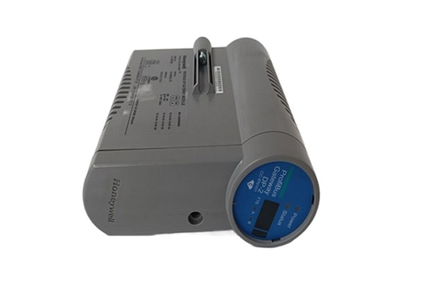


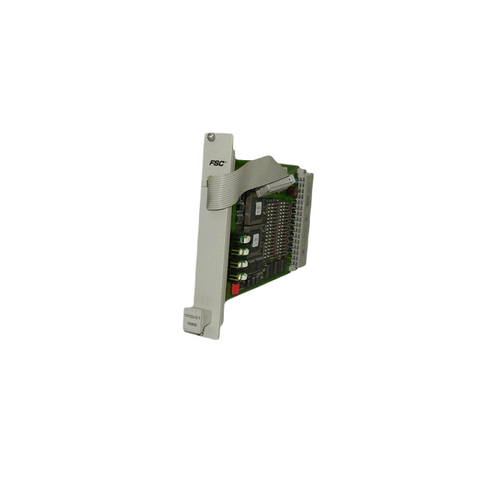
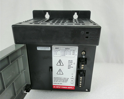
Honeywell 10102/2/1 Fail-Safe analog Input Module (4 channels)
Manufacturer: Honeywell
Product Number: 10102/2/1
Category: Fail-Safe Analog Input Module
System Platform: Honeywell Safety Manager
Number of Channels: 4
Input Signal: 4-20 mA
Safety Integrity Level: SIL 3 capable
Function: Safety-related analog signal acquisition for emergency shutdown applications
Application: Emergency shutdown systems, fire and gas systems, process safety
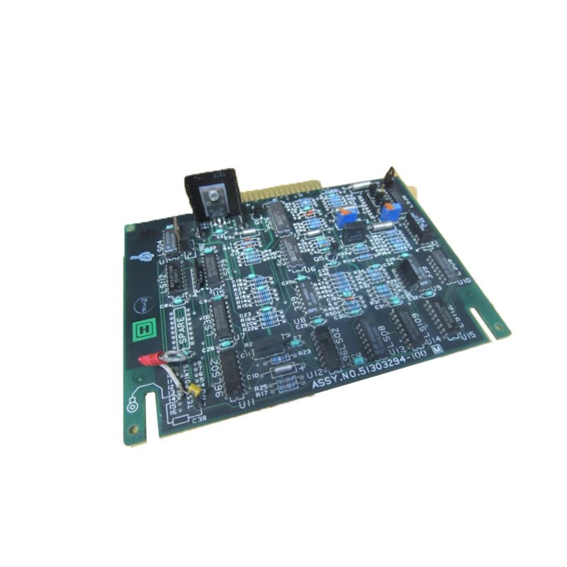
Product Description
The fail-safe analog input module 10102/2/1 is equipped with four 0-2 V analog input channels. These analog inputs share a common 0 V connection but are galvanically isolated from the 24 Vdc and 5 Vdc supplies.
The analog inputs can be used actively, with each input having a separate 26 Vdc, > 20 mA short-circuit protected output, or passively, where the supply is directly connected to the transmitter.
The input stage of 10102/2/1 features a high input impedance, allowing the connection of two 10102/2/1 modules in parallel. However, each input requires an analog input converter module 10102/A/ (refer to the 10102/A/ data sheets).
Note: As the inputs require a 10102/A/ converter module, the 10102/2/1 module can only be used in combination with an I/O backplane in the rack.
The analog input module performs scans on the analog inputs, the 26 V output voltages, internal supply voltages, and a reference voltage generated by a D/A converter. This D/A converter generates various reference voltages used to comprehensively test the analog input module. The self-test includes a leakage test of the input filter, which could affect the accuracy of the analog input value.
Within the configured process safety time, the analog inputs are tested for:
- Absolute accuracy
- Correct conversion over the full range
- Crosstalk between inputs
- Output voltage of the 26 Vdc outputs
The 26 Vdc outputs are generated by the DC/DC converter and stabilized at 26 Vdc, making them independent of the incoming 24 Vdc supply.
Note: The maximum output current is at least 21 mA. If the transmitters require a higher supply current, the input channel must be used in passive mode (= external supply).
Analog Input Ranges for FSC:
Table 1 provides an overview of the analog input ranges for the FSC system and how the 10102/2/1 module can be used for each of these ranges.
Table 1: Overview of analog inputs for FSC
- 0(4)-20 mA Internal power: 10102/2/1 + 10102/A/1
- 0(4)-20 mA External power: 10102/2/1 + 10102/A/2
- 0(1)-5 V External power: 10102/2/1 + 10102/A/3
- 0(2)-10 V External power: 10102/2/1 + 10102/A/4
- Loop-monitored digital input: 10102/2/1 + 10102/A/5
Other analog input signals such as thermocouples, PT-100, etc., can only be used after conversion to one of the analog input ranges that the FSC system can handle.
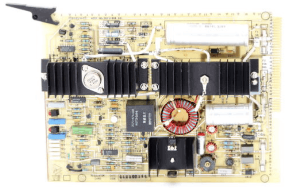
Technical Data
The 10102/2/1 module specifications include:
- General Type number: 10102/2/1 11301*
- Approvals: CE, TÜV, UL
- Software versions: ≥ 3.00
- Space requirements: 4 TE, 3 HE (= 4 HP, 3U)
Power:
- Power requirements: 5 Vdc 30 mA
- 24 Vdc 175 mA + 25 mA for each active input
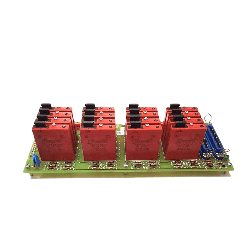
Input:
- Number of input channels: 4
- Input specification (V): 0-2 Vdc
- Input resistance: > 100 kOhm
- Loop powering: 26 Vdc (±1 V for 0.2 mA < I < 20 mA), short-circuit protected
- Loop current limit: > 21 mA solid-state
- A/D converter: 12-bit
- Inaccuracy: ≤ 0.75%
- Absolute max. input signal: ± 5 Vdc
Key Coding: Refer to the ‘Key Coding’ data sheet for details on key coding.
Module Connector Code:
- Holes A5, C17
Rack Connector Code:
- Large pins A5, C17
 Loading comments...

Honeywell 10102/2/1 Fail-Safe analog Input Module (4 channels)
Manufacturer: Honeywell
Product Number: 10102/2/1
Category: Fail-Safe Analog Input Module
System Platform: Honeywell Safety Manager
Number of Channels: 4
Input Signal: 4-20 mA
Safety Integrity Level: SIL 3 capable
Function: Safety-related analog signal acquisition for emergency shutdown applications
Application: Emergency shutdown systems, fire and gas systems, process safety
Product Description
The fail-safe analog input module 10102/2/1 is equipped with four 0-2 V analog input channels. These analog inputs share a common 0 V connection but are galvanically isolated from the 24 Vdc and 5 Vdc supplies.
The analog inputs can be used actively, with each input having a separate 26 Vdc, > 20 mA short-circuit protected output, or passively, where the supply is directly connected to the transmitter.
The input stage of 10102/2/1 features a high input impedance, allowing the connection of two 10102/2/1 modules in parallel. However, each input requires an analog input converter module 10102/A/ (refer to the 10102/A/ data sheets).
Note: As the inputs require a 10102/A/ converter module, the 10102/2/1 module can only be used in combination with an I/O backplane in the rack.
The analog input module performs scans on the analog inputs, the 26 V output voltages, internal supply voltages, and a reference voltage generated by a D/A converter. This D/A converter generates various reference voltages used to comprehensively test the analog input module. The self-test includes a leakage test of the input filter, which could affect the accuracy of the analog input value.
Within the configured process safety time, the analog inputs are tested for:
- Absolute accuracy
- Correct conversion over the full range
- Crosstalk between inputs
- Output voltage of the 26 Vdc outputs
The 26 Vdc outputs are generated by the DC/DC converter and stabilized at 26 Vdc, making them independent of the incoming 24 Vdc supply.
Note: The maximum output current is at least 21 mA. If the transmitters require a higher supply current, the input channel must be used in passive mode (= external supply).
Analog Input Ranges for FSC:
Table 1 provides an overview of the analog input ranges for the FSC system and how the 10102/2/1 module can be used for each of these ranges.
Table 1: Overview of analog inputs for FSC
- 0(4)-20 mA Internal power: 10102/2/1 + 10102/A/1
- 0(4)-20 mA External power: 10102/2/1 + 10102/A/2
- 0(1)-5 V External power: 10102/2/1 + 10102/A/3
- 0(2)-10 V External power: 10102/2/1 + 10102/A/4
- Loop-monitored digital input: 10102/2/1 + 10102/A/5
Other analog input signals such as thermocouples, PT-100, etc., can only be used after conversion to one of the analog input ranges that the FSC system can handle.
Technical Data
The 10102/2/1 module specifications include:
- General Type number: 10102/2/1 11301*
- Approvals: CE, TÜV, UL
- Software versions: ≥ 3.00
- Space requirements: 4 TE, 3 HE (= 4 HP, 3U)
Power:
- Power requirements: 5 Vdc 30 mA
- 24 Vdc 175 mA + 25 mA for each active input
Input:
- Number of input channels: 4
- Input specification (V): 0-2 Vdc
- Input resistance: > 100 kOhm
- Loop powering: 26 Vdc (±1 V for 0.2 mA < I < 20 mA), short-circuit protected
- Loop current limit: > 21 mA solid-state
- A/D converter: 12-bit
- Inaccuracy: ≤ 0.75%
- Absolute max. input signal: ± 5 Vdc
Key Coding: Refer to the ‘Key Coding’ data sheet for details on key coding.
Module Connector Code:
- Holes A5, C17
Rack Connector Code:
- Large pins A5, C17

Need a Custom Automation Solution?
Our team of experts can design and implement a tailored automation system to meet your specific requirements.