Our Products
Comprehensive industrial automation solutions for global industries
Contact us
If you are interested in our products and want to know more details,please Contact us,we will reply you as soon as we can.
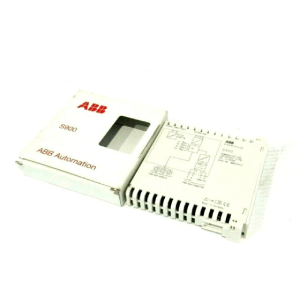
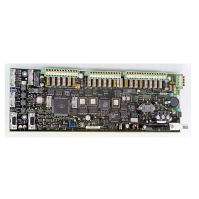
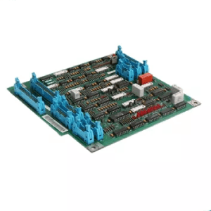
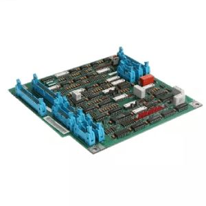
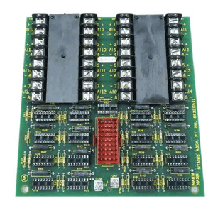
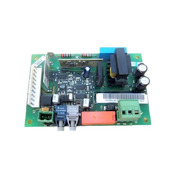
ABB NBRC‑51C Braking Unit Chopper Control Board
Manufacturer:ABB
Product Number:NBRC-51C
Product Type:Braking Unit Chopper Control Board
Origin:Switzerland
Dimensions:22 x 124 x 126mm
Weight:1.5 kg
Views:128
Payment Methods:T/T, PayPal, Western Union
Condition:New & In Stock
Warranty:1 Year
Lead Time:1-3 Working Days
Certificate:COO
Courier partners:DHL, UPS, TNT, FedEx and EMS.
Business hours:7*24
Product Description
The ABB NBRC‑51C is a dedicated braking‑unit chopper control board engineered for ABB low‑voltage drives that operate in applications with frequent deceleration or overhauling loads. By precisely switching the braking transistor and external resistor bank, the NBRC‑51C safely diverts surplus DC‑bus energy, preventing over‑voltage trips and ensuring continuous, reliable drive operation.
Robust multi‑layer PCB construction, industrial‑grade components, and extensive self‑diagnostics make the board a dependable choice for harsh environments where thermal cycling, vibration, and electrical noise are commonplace. Its compact footprint allows easy retro‑fit or new‑build integration, reducing engineering time and cabinet space requirements while enhancing overall system safety.
Product Parameters
| Parameter | Specification |
|---|---|
| Model Number | NBRC‑51C |
| Function | Braking‑chopper control for external resistor banks |
| Applicable Drive Series | ABB ACS580 / ACS880 and compatible low‑voltage drives |
| Nominal DC‑Bus Voltage | 500 – 840 V DC (drive dependent) |
| Peak Braking Current | 100 A (continuous) / 200 A (peak, ≤ 10 s) |
| Switching Device | IGBT, soft‑gate control |
| Protection Features | Over‑current, over‑temperature, resistor open/short detection |
| Control Interface | Opto‑isolated PWM from drive CPU |
| Status Indication | On‑board tri‑colour LED (Ready / Active / Fault) |
| Operating Temperature | −25 °C … +60 °C |
| Storage Temperature | −40 °C … +85 °C |
| Humidity Tolerance | 5 % … 95 % RH, non‑condensing |
| Cooling Requirement | Conduction to drive heatsink; optional forced air |
| Mounting Method | Four‑point screw, M3, within drive enclosure |
| Dimensions (L × W × H) | 22 × 124 × 126 mm |
| Weight | 1.5 kg |
| Compliance | CE, UL, RoHS, IEC 61800‑5‑1 safety |
Product Applications
-
Cranes & Hoists: Controls regenerative energy generated during rapid lowering of heavy loads, preventing DC‑bus over‑voltage trips and ensuring smooth, uninterrupted crane motion.
-
Elevators & Escalators: Handles continuous braking cycles, improving ride comfort and extending mechanical brake life.
-
Centrifuges & Spindles: Manages fast deceleration sequences, keeping production lines within strict takt times.
-
Winders & Unwinders: Absorbs torque peaks when switching from motoring to braking in paper, film, and textile processing.
-
Test Benches & Dynamometers: Enables safe energy dissipation during rapid speed sweeps and emergency stops.
-
Pumping Systems on Declines: Protects drives in downhill conveyors or pipeline pumps where the load can regenerate power back into the drive.
Product Advantages
-
Superior Thermal Management – Thick copper planes and generous heat‑spreading area allow sustained high braking currents without derating.
-
Precision Switching – Opto‑isolated gate drivers minimise propagation delay, ensuring stable DC‑bus voltage under dynamic load changes.
-
Comprehensive Diagnostics – Real‑time fault codes, LED status, and field‑bus reporting speed up troubleshooting and reduce downtime.
-
Space‑Saving Design – 22 mm thickness permits installation in tight drive sections, freeing cabinet space for ancillary equipment.
-
Extended Component Life – Conservative voltage derating and conformal coating enhance resistance to moisture, dust, and corrosives.
-
Plug‑and‑Play Integration – Pre‑configured parameter sets in ABB drives recognise the NBRC‑51C automatically—no extra commissioning tools required.
-
Energy Efficiency – Chopper algorithm minimises average resistor dissipation, reducing enclosure heat load and ventilation costs.
-
Global Compliance – Meets major international safety and EMC standards, simplifying export projects and regulatory approvals.
Frequently Asked Questions (FAQ)
Q1: What does the NBRC‑51C actually do inside my drive?
A1: It detects rising DC‑bus voltage during regeneration and pulses the braking transistor, directing excess energy into an external resistor so the drive can keep running.
Q2: Can one board drive multiple resistor banks?
A2: The NBRC‑51C controls a single resistor circuit; multiple banks require parallel boards or a suitably rated single resistor stack.
Q3: How do I know if my application needs a braking chopper?
A3: Any process with frequent or rapid deceleration, overhauling loads, or bidirectional torque generally benefits from a chopper–resistor combination.
Q4: Is special firmware needed in the drive?
A4: No. Standard ACS580/ACS880 firmware automatically recognises and configures the NBRC‑51C once wired.
Q5: What happens if the resistor goes open‑circuit?
A5: The board raises a fault, disables the chopper, and signals the drive to decelerate using alternative methods to protect the equipment.
Q6: Can the NBRC‑51C be field‑repaired?
A6: Only connector changes and fuse replacement are field‑serviceable; semiconductor or logic repairs must be performed at an ABB service centre.
Q7: Does installing the board affect EMC performance?
A7: No, it is designed to maintain the drive’s original EMC compliance when installed according to the wiring guidelines.
Q8: What maintenance does the board require?
A8: Periodic visual inspection for dust and loose connections; no routine calibration or firmware updates are needed.
Q9: Can I monitor chopper activity remotely?
A9: Yes, the board’s status is mapped to the drive’s field‑bus registers, allowing SCADA or PLC monitoring.
Q10: Is additional cooling ever necessary?
A10: For continuous high‑energy braking, supplemental airflow across the resistor and drive heatsink is recommended to maintain safe temperatures.
 Loading comments...
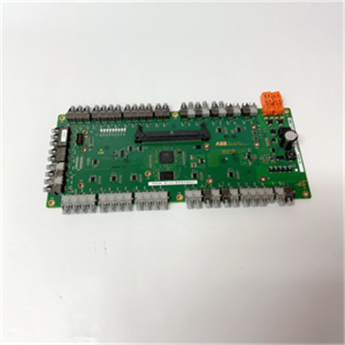
ABB NBRC‑51C Braking Unit Chopper Control Board
Manufacturer:ABB
Product Number:NBRC-51C
Product Type:Braking Unit Chopper Control Board
Origin:Switzerland
Dimensions:22 x 124 x 126mm
Weight:1.5 kg
Views:128
Payment Methods:T/T, PayPal, Western Union
Condition:New & In Stock
Warranty:1 Year
Lead Time:1-3 Working Days
Certificate:COO
Courier partners:DHL, UPS, TNT, FedEx and EMS.
Business hours:7*24
Product Description
The ABB NBRC‑51C is a dedicated braking‑unit chopper control board engineered for ABB low‑voltage drives that operate in applications with frequent deceleration or overhauling loads. By precisely switching the braking transistor and external resistor bank, the NBRC‑51C safely diverts surplus DC‑bus energy, preventing over‑voltage trips and ensuring continuous, reliable drive operation.
Robust multi‑layer PCB construction, industrial‑grade components, and extensive self‑diagnostics make the board a dependable choice for harsh environments where thermal cycling, vibration, and electrical noise are commonplace. Its compact footprint allows easy retro‑fit or new‑build integration, reducing engineering time and cabinet space requirements while enhancing overall system safety.
Product Parameters
| Parameter | Specification |
|---|---|
| Model Number | NBRC‑51C |
| Function | Braking‑chopper control for external resistor banks |
| Applicable Drive Series | ABB ACS580 / ACS880 and compatible low‑voltage drives |
| Nominal DC‑Bus Voltage | 500 – 840 V DC (drive dependent) |
| Peak Braking Current | 100 A (continuous) / 200 A (peak, ≤ 10 s) |
| Switching Device | IGBT, soft‑gate control |
| Protection Features | Over‑current, over‑temperature, resistor open/short detection |
| Control Interface | Opto‑isolated PWM from drive CPU |
| Status Indication | On‑board tri‑colour LED (Ready / Active / Fault) |
| Operating Temperature | −25 °C … +60 °C |
| Storage Temperature | −40 °C … +85 °C |
| Humidity Tolerance | 5 % … 95 % RH, non‑condensing |
| Cooling Requirement | Conduction to drive heatsink; optional forced air |
| Mounting Method | Four‑point screw, M3, within drive enclosure |
| Dimensions (L × W × H) | 22 × 124 × 126 mm |
| Weight | 1.5 kg |
| Compliance | CE, UL, RoHS, IEC 61800‑5‑1 safety |
Product Applications
-
Cranes & Hoists: Controls regenerative energy generated during rapid lowering of heavy loads, preventing DC‑bus over‑voltage trips and ensuring smooth, uninterrupted crane motion.
-
Elevators & Escalators: Handles continuous braking cycles, improving ride comfort and extending mechanical brake life.
-
Centrifuges & Spindles: Manages fast deceleration sequences, keeping production lines within strict takt times.
-
Winders & Unwinders: Absorbs torque peaks when switching from motoring to braking in paper, film, and textile processing.
-
Test Benches & Dynamometers: Enables safe energy dissipation during rapid speed sweeps and emergency stops.
-
Pumping Systems on Declines: Protects drives in downhill conveyors or pipeline pumps where the load can regenerate power back into the drive.
Product Advantages
-
Superior Thermal Management – Thick copper planes and generous heat‑spreading area allow sustained high braking currents without derating.
-
Precision Switching – Opto‑isolated gate drivers minimise propagation delay, ensuring stable DC‑bus voltage under dynamic load changes.
-
Comprehensive Diagnostics – Real‑time fault codes, LED status, and field‑bus reporting speed up troubleshooting and reduce downtime.
-
Space‑Saving Design – 22 mm thickness permits installation in tight drive sections, freeing cabinet space for ancillary equipment.
-
Extended Component Life – Conservative voltage derating and conformal coating enhance resistance to moisture, dust, and corrosives.
-
Plug‑and‑Play Integration – Pre‑configured parameter sets in ABB drives recognise the NBRC‑51C automatically—no extra commissioning tools required.
-
Energy Efficiency – Chopper algorithm minimises average resistor dissipation, reducing enclosure heat load and ventilation costs.
-
Global Compliance – Meets major international safety and EMC standards, simplifying export projects and regulatory approvals.
Frequently Asked Questions (FAQ)
Q1: What does the NBRC‑51C actually do inside my drive?
A1: It detects rising DC‑bus voltage during regeneration and pulses the braking transistor, directing excess energy into an external resistor so the drive can keep running.
Q2: Can one board drive multiple resistor banks?
A2: The NBRC‑51C controls a single resistor circuit; multiple banks require parallel boards or a suitably rated single resistor stack.
Q3: How do I know if my application needs a braking chopper?
A3: Any process with frequent or rapid deceleration, overhauling loads, or bidirectional torque generally benefits from a chopper–resistor combination.
Q4: Is special firmware needed in the drive?
A4: No. Standard ACS580/ACS880 firmware automatically recognises and configures the NBRC‑51C once wired.
Q5: What happens if the resistor goes open‑circuit?
A5: The board raises a fault, disables the chopper, and signals the drive to decelerate using alternative methods to protect the equipment.
Q6: Can the NBRC‑51C be field‑repaired?
A6: Only connector changes and fuse replacement are field‑serviceable; semiconductor or logic repairs must be performed at an ABB service centre.
Q7: Does installing the board affect EMC performance?
A7: No, it is designed to maintain the drive’s original EMC compliance when installed according to the wiring guidelines.
Q8: What maintenance does the board require?
A8: Periodic visual inspection for dust and loose connections; no routine calibration or firmware updates are needed.
Q9: Can I monitor chopper activity remotely?
A9: Yes, the board’s status is mapped to the drive’s field‑bus registers, allowing SCADA or PLC monitoring.
Q10: Is additional cooling ever necessary?
A10: For continuous high‑energy braking, supplemental airflow across the resistor and drive heatsink is recommended to maintain safe temperatures.
Need a Custom Automation Solution?
Our team of experts can design and implement a tailored automation system to meet your specific requirements.