Our Products
Comprehensive industrial automation solutions for global industries
Contact us
If you are interested in our products and want to know more details,please Contact us,we will reply you as soon as we can.
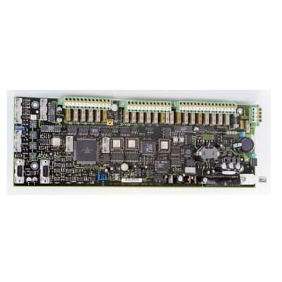
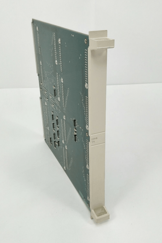
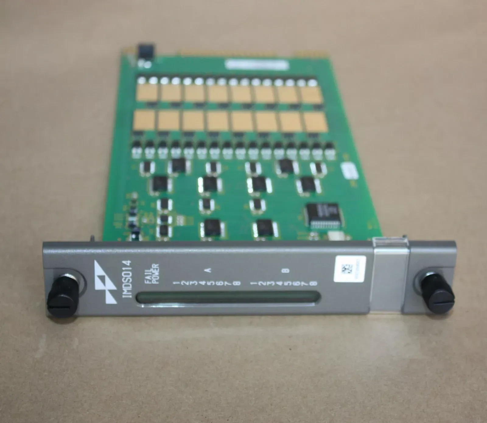
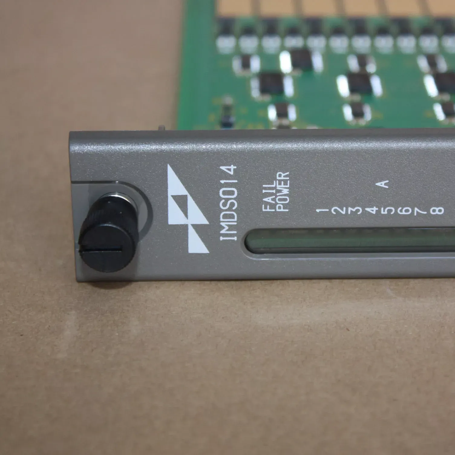
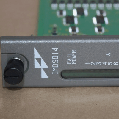
ABB IMDSO14 Digital Slave Output Module
Item Number:IMDSO14
Brand: ABB
Lead Time: In stock
Description:Digital Slave Output Module
Payment: T/T
Product Description
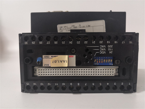
ABB IMDSO14 digital output (DSO) module consists of a printed circuit board (PCB) that fits into a single slot of a module mounting unit (MMU). The module is designed to provide 16 digital output signals for field device control in process control systems. Its features are remarkable, based on a PCB design, and the 16 digital output signals are generated by onboard solid-state circuits, which can achieve digital switching of on or off. The 12 outputs are isolated from each other to ensure independent signal operation, and the other two pairs of outputs share the positive line.
Fuctions & Features
- PCB Design: The DSO module is built on a printed circuit board (PCB) that contains solid-state circuits responsible for generating the 16 digital output signals.
- 16 Digital Outputs: These signals are provided by solid-state circuits on the board, which can be ON or OFF (digital switching).
- Isolation: 12 outputs are isolated from each other, ensuring that each signal operates independently. The remaining two pairs of outputs share common positive lines.
- Faceplate and LEDs:The module is secured to the MMU by two captive screws on the faceplate. These screws help to securely mount the module within the unit.The upper two front panel LEDs (red and green) indicate the operating status of the module (whether it is functioning properly or encountering an issue).The 16 lower front panel LEDs are grouped into Group A and Group B, and they display the ON or OFF state of each of the 16 output channels, providing real-time feedback on the module's performance.
Connectors and Power Distribution
The IMDSO14 Digital Output (DSO) Module has three card edge connectors that provide the necessary external connections for power and signal communication:
P1: Connects to logic power (+5 VDC) which powers the module's internal circuits and functionality.
P2: Connects the module to the I/O expander bus, allowing communication with the control module and enabling the module to receive commands or data.
P3: Outputs the digital signals through a cable that connects to a termination unit (TU) or termination module (TM). These termination units are responsible for physically connecting the module to the field wiring.
Field Wiring and Termination Units:The termination unit (TU) or termination module (TM) provides the physical connection points (terminals) for field wiring. These wiring points allow the digital output signals to be routed to the appropriate field devices, such as valves, actuators, or relays.
Specification
|
Parameter |
Details |
|
Power Requirements - Voltage |
5 VDC (±5%) |
|
Power Requirements - Current |
275 mA (typical), 370 mA (maximum) |
|
Power Requirements - Dissipation (logic only) |
1.375 W (typical), 1.850 W (maximum) |
|
Overvoltage Category on Outputs |
II, per IEC 1010-1 |
|
Outputs |
16 digital |
|
Load Voltage |
24 VDC, 48 VDC |
|
Load Current (maximum) |
250 mA (24 VDC), 125 mA (48 VDC) |
|
Off Leakage Current (maximum) |
10 µA at 70°C (158°F) |
|
On Voltage Drop (maximum) |
2 V at 70°C (158°F) |
|
Current Consumption |
150 mA (typical), 250 mA (maximum) per output at 24 VDC |
 Loading comments...
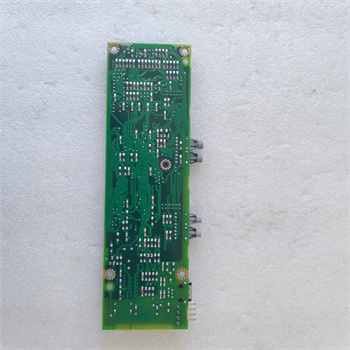
ABB IMDSO14 Digital Slave Output Module
Item Number:IMDSO14
Brand: ABB
Lead Time: In stock
Description:Digital Slave Output Module
Payment: T/T
Product Description
ABB IMDSO14 digital output (DSO) module consists of a printed circuit board (PCB) that fits into a single slot of a module mounting unit (MMU). The module is designed to provide 16 digital output signals for field device control in process control systems. Its features are remarkable, based on a PCB design, and the 16 digital output signals are generated by onboard solid-state circuits, which can achieve digital switching of on or off. The 12 outputs are isolated from each other to ensure independent signal operation, and the other two pairs of outputs share the positive line.
Fuctions & Features
- PCB Design: The DSO module is built on a printed circuit board (PCB) that contains solid-state circuits responsible for generating the 16 digital output signals.
- 16 Digital Outputs: These signals are provided by solid-state circuits on the board, which can be ON or OFF (digital switching).
- Isolation: 12 outputs are isolated from each other, ensuring that each signal operates independently. The remaining two pairs of outputs share common positive lines.
- Faceplate and LEDs:The module is secured to the MMU by two captive screws on the faceplate. These screws help to securely mount the module within the unit.The upper two front panel LEDs (red and green) indicate the operating status of the module (whether it is functioning properly or encountering an issue).The 16 lower front panel LEDs are grouped into Group A and Group B, and they display the ON or OFF state of each of the 16 output channels, providing real-time feedback on the module's performance.
Connectors and Power Distribution
The IMDSO14 Digital Output (DSO) Module has three card edge connectors that provide the necessary external connections for power and signal communication:
P1: Connects to logic power (+5 VDC) which powers the module's internal circuits and functionality.
P2: Connects the module to the I/O expander bus, allowing communication with the control module and enabling the module to receive commands or data.
P3: Outputs the digital signals through a cable that connects to a termination unit (TU) or termination module (TM). These termination units are responsible for physically connecting the module to the field wiring.
Field Wiring and Termination Units:The termination unit (TU) or termination module (TM) provides the physical connection points (terminals) for field wiring. These wiring points allow the digital output signals to be routed to the appropriate field devices, such as valves, actuators, or relays.
Specification
|
Parameter |
Details |
|
Power Requirements - Voltage |
5 VDC (±5%) |
|
Power Requirements - Current |
275 mA (typical), 370 mA (maximum) |
|
Power Requirements - Dissipation (logic only) |
1.375 W (typical), 1.850 W (maximum) |
|
Overvoltage Category on Outputs |
II, per IEC 1010-1 |
|
Outputs |
16 digital |
|
Load Voltage |
24 VDC, 48 VDC |
|
Load Current (maximum) |
250 mA (24 VDC), 125 mA (48 VDC) |
|
Off Leakage Current (maximum) |
10 µA at 70°C (158°F) |
|
On Voltage Drop (maximum) |
2 V at 70°C (158°F) |
|
Current Consumption |
150 mA (typical), 250 mA (maximum) per output at 24 VDC |
Need a Custom Automation Solution?
Our team of experts can design and implement a tailored automation system to meet your specific requirements.