Our Products
Comprehensive industrial automation solutions for global industries
Contact us
If you are interested in our products and want to know more details,please Contact us,we will reply you as soon as we can.
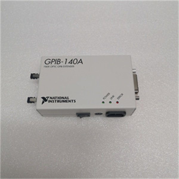
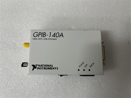
NI GPIB-140A2 GPIB extender
Manufacturer:NI
Product Number:NI GPIB-140A2
Payment Methods:T/T, PayPal, Western Union
Condition:New & In Stock
Warranty:1 Year
Lead Time:1-3 Working Days
Certificate:COO
Courier partners:DHL, UPS, TNT, FedEx and EMS.
Business hours:7*24
Product Description
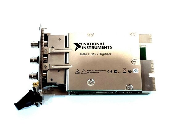
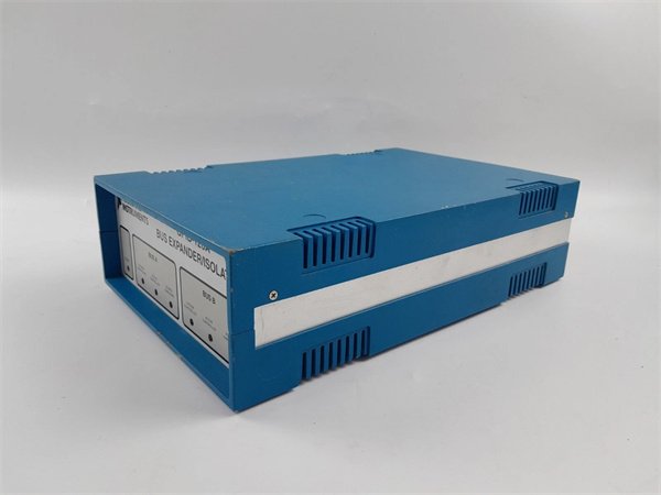
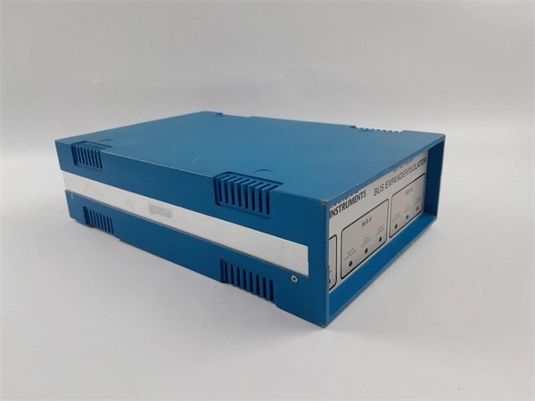
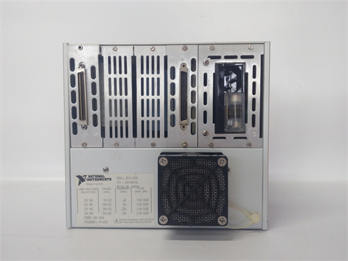
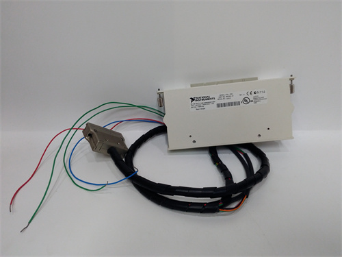
The NI GPIB-140A2 is a high-performance fiber-optic GPIB extender designed to overcome the distance and device-count limitations of traditional GPIB systems. As a key component in National Instruments’ GPIB ecosystem, it enables long-range communication between GPIB-enabled instruments and controllers, extending cable lengths from the standard 20 m (IEEE 488) to an impressive 2 km.
By leveraging fiber-optic technology, the GPIB-140A2 eliminates electromagnetic interference (EMI) and radio-frequency interference (RFI) issues common in copper-based GPIB cables, ensuring reliable data transmission in electrically noisy environments. It supports both standard IEEE 488.1 and high-speed HS488 protocols, making it compatible with legacy and modern GPIB instruments alike. Whether deployed in large industrial plants, research laboratories, or distributed test facilities, the GPIB-140A2 simplifies system expansion while maintaining signal integrity.
Detailed Parameter Table
| Parameter Name | Parameter Value |
| Product Model | GPIB-140A2 |
| Manufacturer | National Instruments |
| Product Category | GPIB extender (fiber-optic based) |
| Communication Standard | IEEE 488.1, HS488 |
| Data Transfer Rates | Up to 1.1 Mbytes/s (IEEE 488.1); up to 2.8 Mbytes/s (HS488) |
| Maximum Extension Distance | 2 km (using Type T8 fiber-optic cable) |
| Maximum Device Capacity | 28 devices (13 additional per extender, beyond the 15-device IEEE 488 limit) |
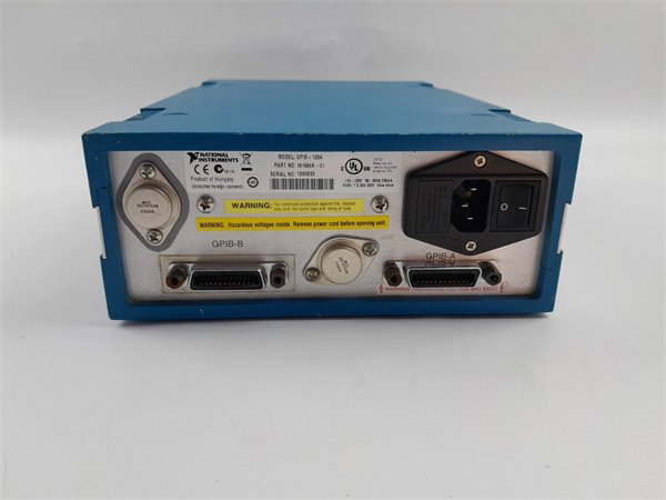
| Power Requirements | Multiple options: 120 VAC (US), 220 VAC (Swiss), 240 VAC (Australian, Euro, UK, North American) |
| Power Part Numbers | 777998-01 (US 120V), 777998-02 (Swiss 220V), 777998-03 (Australian 240V), 777998-04 (Euro 240V), 777998-05 (NA 240V), 777998-06 (UK 240V) |
| Cable Type | Type T8 fiber-optic cable (single-mode) |
| Enclosure | All-metal, EMI/RFI shielded |
| Operating Temperature | 0 °C to 55 °C |
| Storage Temperature | -20 °C to 70 °C |
| Humidity Range | 5% to 95% (non-condensing) |
| Dimensions | 190 mm x 130 mm x 45 mm |
| Weight | 500 g |
| Compliance Standards | CE, UL, CSA, FCC Part 15 Class A |
Core Advantages and Technical Highlights
Fiber-Optic Reliability
The GPIB-140A2’s fiber-optic transmission medium is inherently immune to EMI/RFI, a critical advantage in environments with heavy machinery, power lines, or radio transmitters. Unlike copper cables, which can pick up noise and degrade signals over distance, fiber optics ensure stable data transfer even in harsh industrial settings—such as automotive factories or power generation facilities—where electrical interference is prevalent.
Extended Reach and Scalability
Breaking the 20 m barrier of standard GPIB, the GPIB-140A2 enables instrument placement up to 2 km from controllers. This is transformative for large-scale setups, such as aerospace test ranges where sensors and analyzers may be spread across a facility. Additionally, it increases the maximum number of connected devices from 15 to 28, allowing users to build more complex systems without sacrificing performance—a boon for semiconductor wafer test stations or multi-channel data acquisition systems.
Dual Transmission Modes
The extender offers buffered and unbuffered modes to optimize performance for different scenarios:
Buffered mode: Uses FIFO buffers to boost throughput, ideal for high-speed data acquisition from oscilloscopes or spectrum analyzers.
Unbuffered mode: Ensures bit-by-bit verification, critical for command/response applications like programmable power supplies where data accuracy is paramount.
Users can switch modes via DIP switches, tailoring the device to specific test requirements.
Robust Design
Encased in an all-metal housing, the GPIB-140A2 withstands physical stress and provides additional EMI shielding. Its wide operating temperature range (0 °C to 55 °C) ensures reliability in both climate-controlled labs and unconditioned industrial spaces, while compliance with global safety standards (CE, UL, CSA) simplifies deployment in international markets.
Typical Application Scenarios
In automotive manufacturing, the GPIB-140A2 connects a central test controller to measurement instruments (e.g., multimeters, torque sensors) spread across a production line. Its 2 km range allows placement of sensitive equipment away from assembly-line noise, while fiber optics prevent interference from welding robots or motors.
In academic research, a physics laboratory might use the extender to link a control computer to detectors in a radiation-shielded room or vacuum chamber. The EMI immunity ensures accurate data from particle counters or spectrometers, even when located hundreds of meters from the lab.
In broadcast facilities, the GPIB-140A2 integrates signal analyzers, signal generators, and transmitters across a campus. Its ability to support 28 devices enables centralized monitoring of multiple transmitters, while the fiber-optic link avoids interference from radio towers.
Installation Commissioning, and Maintenance
Installation Steps
Power Preparation: Select the correct power supply (e.g., 777998-01 for 120 VAC in the US) and ensure the outlet is grounded.
Mounting: Place the GPIB-140A2 in a dry, dust-free location—rack-mount or bench-top—with ventilation clearance.
Cabling: Connect Type T8 fiber-optic cables between the extender and GPIB instruments/controllers. Use fiber-optic cleaning kits to ensure connector cleanliness.
Configuration: Set DIP switches for buffered/unbuffered mode (default: unbuffered) and power on the device.
Commissioning
Use NI MAX (Measurement & Automation Explorer) to verify GPIB device detection across the extended network.
Test data transfer with a sample instrument (e.g., send a *IDN? query to a spectrum analyzer) to confirm communication.
Validate HS488 performance by transferring a large dataset (e.g., waveform capture from an oscilloscope) in buffered mode.
Maintenance Tips
Inspect fiber-optic connectors monthly for dust or damage; clean with approved fiber cleaners.
Check power connections quarterly to prevent corrosion, especially in humid environments.
Store spare Type T8 cables in protective cases to avoid fiber breakage.
If communication fails, reset the extender and verify DIP switch settings; replace cables if signal loss is detected.
 Loading comments...
NI GPIB-140A2 GPIB extender
Manufacturer:NI
Product Number:NI GPIB-140A2
Payment Methods:T/T, PayPal, Western Union
Condition:New & In Stock
Warranty:1 Year
Lead Time:1-3 Working Days
Certificate:COO
Courier partners:DHL, UPS, TNT, FedEx and EMS.
Business hours:7*24
Product Description
The NI GPIB-140A2 is a high-performance fiber-optic GPIB extender designed to overcome the distance and device-count limitations of traditional GPIB systems. As a key component in National Instruments’ GPIB ecosystem, it enables long-range communication between GPIB-enabled instruments and controllers, extending cable lengths from the standard 20 m (IEEE 488) to an impressive 2 km.
By leveraging fiber-optic technology, the GPIB-140A2 eliminates electromagnetic interference (EMI) and radio-frequency interference (RFI) issues common in copper-based GPIB cables, ensuring reliable data transmission in electrically noisy environments. It supports both standard IEEE 488.1 and high-speed HS488 protocols, making it compatible with legacy and modern GPIB instruments alike. Whether deployed in large industrial plants, research laboratories, or distributed test facilities, the GPIB-140A2 simplifies system expansion while maintaining signal integrity.
Detailed Parameter Table
| Parameter Name | Parameter Value |
| Product Model | GPIB-140A2 |
| Manufacturer | National Instruments |
| Product Category | GPIB extender (fiber-optic based) |
| Communication Standard | IEEE 488.1, HS488 |
| Data Transfer Rates | Up to 1.1 Mbytes/s (IEEE 488.1); up to 2.8 Mbytes/s (HS488) |
| Maximum Extension Distance | 2 km (using Type T8 fiber-optic cable) |
| Maximum Device Capacity | 28 devices (13 additional per extender, beyond the 15-device IEEE 488 limit) |
| Power Requirements | Multiple options: 120 VAC (US), 220 VAC (Swiss), 240 VAC (Australian, Euro, UK, North American) |
| Power Part Numbers | 777998-01 (US 120V), 777998-02 (Swiss 220V), 777998-03 (Australian 240V), 777998-04 (Euro 240V), 777998-05 (NA 240V), 777998-06 (UK 240V) |
| Cable Type | Type T8 fiber-optic cable (single-mode) |
| Enclosure | All-metal, EMI/RFI shielded |
| Operating Temperature | 0 °C to 55 °C |
| Storage Temperature | -20 °C to 70 °C |
| Humidity Range | 5% to 95% (non-condensing) |
| Dimensions | 190 mm x 130 mm x 45 mm |
| Weight | 500 g |
| Compliance Standards | CE, UL, CSA, FCC Part 15 Class A |
Core Advantages and Technical Highlights
Fiber-Optic Reliability
The GPIB-140A2’s fiber-optic transmission medium is inherently immune to EMI/RFI, a critical advantage in environments with heavy machinery, power lines, or radio transmitters. Unlike copper cables, which can pick up noise and degrade signals over distance, fiber optics ensure stable data transfer even in harsh industrial settings—such as automotive factories or power generation facilities—where electrical interference is prevalent.
Extended Reach and Scalability
Breaking the 20 m barrier of standard GPIB, the GPIB-140A2 enables instrument placement up to 2 km from controllers. This is transformative for large-scale setups, such as aerospace test ranges where sensors and analyzers may be spread across a facility. Additionally, it increases the maximum number of connected devices from 15 to 28, allowing users to build more complex systems without sacrificing performance—a boon for semiconductor wafer test stations or multi-channel data acquisition systems.
Dual Transmission Modes
The extender offers buffered and unbuffered modes to optimize performance for different scenarios:
Buffered mode: Uses FIFO buffers to boost throughput, ideal for high-speed data acquisition from oscilloscopes or spectrum analyzers.
Unbuffered mode: Ensures bit-by-bit verification, critical for command/response applications like programmable power supplies where data accuracy is paramount.
Users can switch modes via DIP switches, tailoring the device to specific test requirements.
Robust Design
Encased in an all-metal housing, the GPIB-140A2 withstands physical stress and provides additional EMI shielding. Its wide operating temperature range (0 °C to 55 °C) ensures reliability in both climate-controlled labs and unconditioned industrial spaces, while compliance with global safety standards (CE, UL, CSA) simplifies deployment in international markets.
Typical Application Scenarios
In automotive manufacturing, the GPIB-140A2 connects a central test controller to measurement instruments (e.g., multimeters, torque sensors) spread across a production line. Its 2 km range allows placement of sensitive equipment away from assembly-line noise, while fiber optics prevent interference from welding robots or motors.
In academic research, a physics laboratory might use the extender to link a control computer to detectors in a radiation-shielded room or vacuum chamber. The EMI immunity ensures accurate data from particle counters or spectrometers, even when located hundreds of meters from the lab.
In broadcast facilities, the GPIB-140A2 integrates signal analyzers, signal generators, and transmitters across a campus. Its ability to support 28 devices enables centralized monitoring of multiple transmitters, while the fiber-optic link avoids interference from radio towers.
Installation Commissioning, and Maintenance
Installation Steps
Power Preparation: Select the correct power supply (e.g., 777998-01 for 120 VAC in the US) and ensure the outlet is grounded.
Mounting: Place the GPIB-140A2 in a dry, dust-free location—rack-mount or bench-top—with ventilation clearance.
Cabling: Connect Type T8 fiber-optic cables between the extender and GPIB instruments/controllers. Use fiber-optic cleaning kits to ensure connector cleanliness.
Configuration: Set DIP switches for buffered/unbuffered mode (default: unbuffered) and power on the device.
Commissioning
Use NI MAX (Measurement & Automation Explorer) to verify GPIB device detection across the extended network.
Test data transfer with a sample instrument (e.g., send a *IDN? query to a spectrum analyzer) to confirm communication.
Validate HS488 performance by transferring a large dataset (e.g., waveform capture from an oscilloscope) in buffered mode.
Maintenance Tips
Inspect fiber-optic connectors monthly for dust or damage; clean with approved fiber cleaners.
Check power connections quarterly to prevent corrosion, especially in humid environments.
Store spare Type T8 cables in protective cases to avoid fiber breakage.
If communication fails, reset the extender and verify DIP switch settings; replace cables if signal loss is detected.
Need a Custom Automation Solution?
Our team of experts can design and implement a tailored automation system to meet your specific requirements.