Our Products
Comprehensive industrial automation solutions for global industries
Contact us
If you are interested in our products and want to know more details,please Contact us,we will reply you as soon as we can.

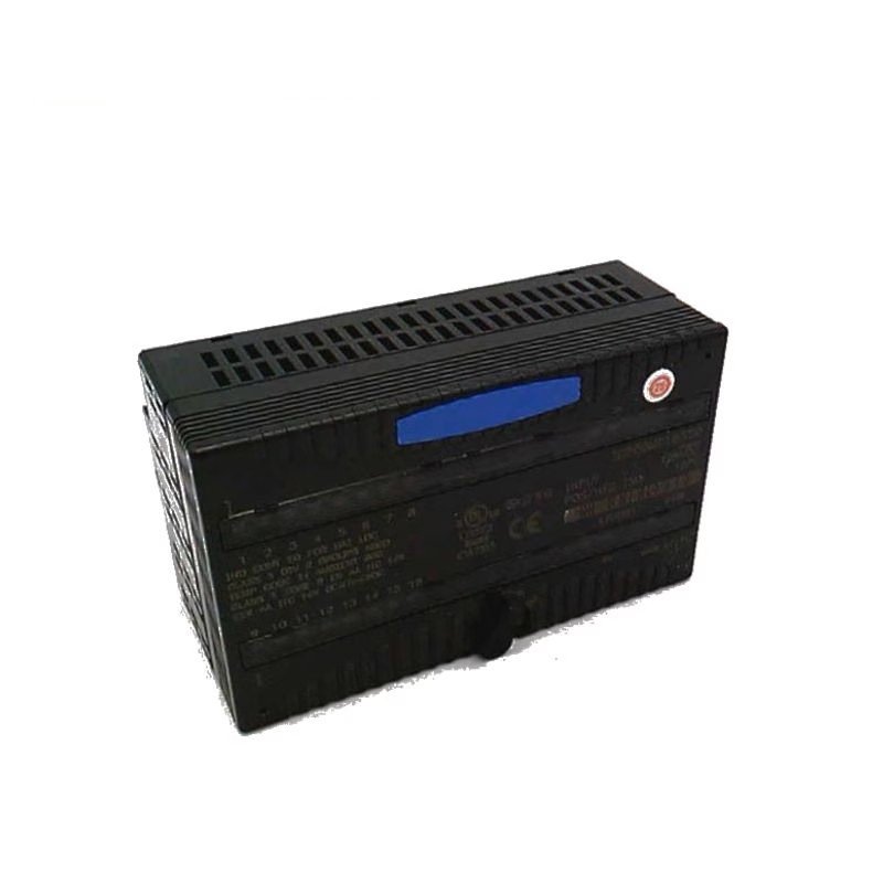
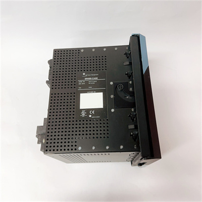
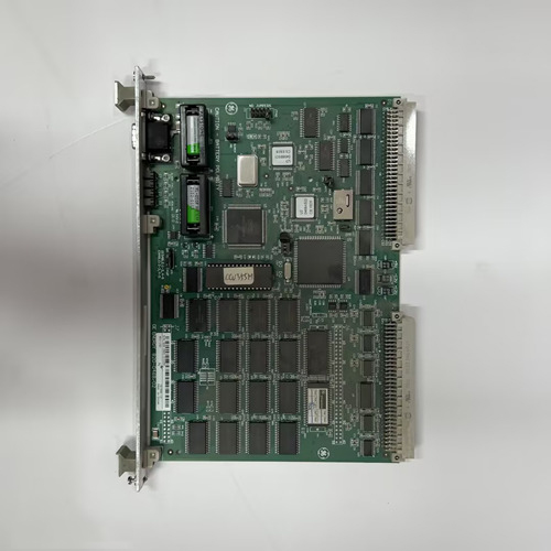
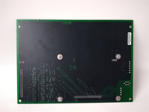
General Electric V7768-322001 350-9301007768-32200 Anti Electromagnetic Interference Module
Manufacturer: General Electric (GE Fanuc / VMIC)
Product Number: V7768-322001
Category: VMEbus Single Board Computer / System Module
Processor: Intel Core 2 Duo
Memory: 4 GB DDR2 RAM
Bus Interface: VME64 (VMEbus)
Features: Anti-electromagnetic interference design for harsh industrial environments
Application: Industrial computing, real-time systems, data acquisition, embedded control
Product Description
The purpose of grounding is usually twofold, one is for safety, and the other is to suppress interference. A sound grounding system is one of the important measures for V7768-322001 control systems to resist electromagnetic interference.
There are three grounding methods for the system: floating grounding, direct grounding, and capacitor grounding. The PLC control system belongs to high-speed low-level control devices and should be directly grounded. Due to the influence of distributed capacitance of signal cables and filtering of input devices, the signal exchange frequency between devices is generally below 1MHz. Therefore, the grounding wire of V7768-322001 control systems is generally grounded at one point or connected in series at one point. It is best to ground it separately or to ground it together with other devices, but it is strictly prohibited to connect it in series with other devices. The centrally arranged PLC system is suitable for parallel one point grounding, and the central grounding point of each device’s cabinet is led to the grounding electrode with a separate grounding wire. If the distance between devices is large, a series grounding method should be adopted, which is to connect a large cross-section copper busbar (or insulated cable) to the center grounding point of each device’s cabinet, and then directly connect the grounding busbar to the grounding electrode. The grounding wire adopts copper wires with a cross-sectional area greater than 20mm2, and the total busbar uses copper bars with a cross-sectional area greater than 60mm2. The grounding resistance of the grounding electrode should be less than 2 Ω. It is best to bury the grounding electrode 10-15m away from the building, and the grounding point of the 350-9301007768-322001 A2 system must be at least 10m away from the grounding point of the strong current equipment.
When the signal source is grounded, the shielding layer should be grounded on the signal side, and when not grounded, it should be grounded on the 350-9301007768-322001 A2 side. When there is a joint in the middle of the signal line, the shielding layer should be firmly connected and insulated, and multiple grounding points must be avoided. When connecting shielded twisted pair signals from multiple measurement points to multi-core twisted pair main screen cables, the shielding layers should be well connected and insulated. When connecting the grounding wire, the following points should be noted:
① The PLC control system is grounded separately.
② The grounding terminal of the PLC system is an anti-interference neutral terminal, and proper grounding can effectively eliminate common mode interference in the power system.
③ The grounding wire of the PLC system should be a dedicated grounding wire of at least 20mm2 to prevent the generation of induced electricity.
④ The shielding wire of the input/output signal cable should be connected to the grounding terminal and well grounded.
 Loading comments...
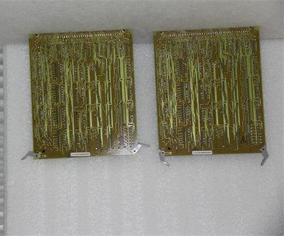
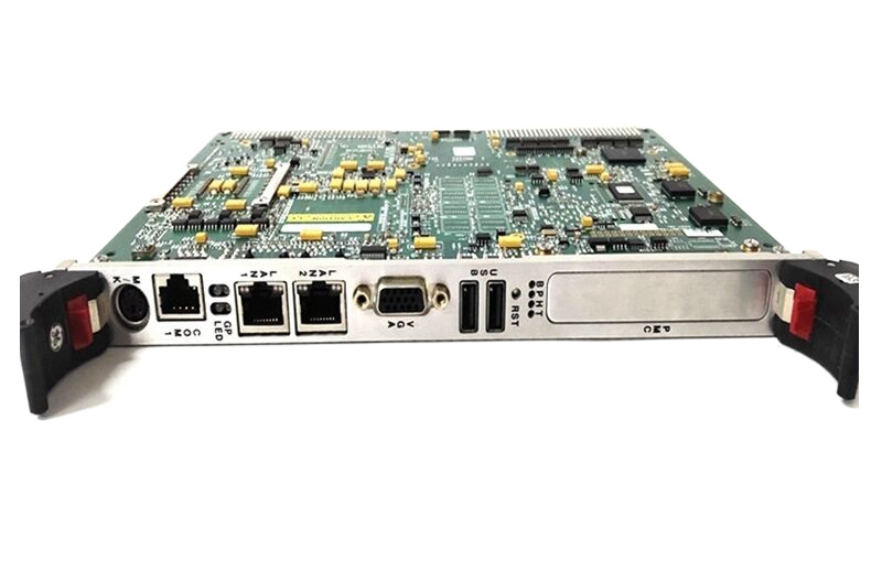
General Electric V7768-322001 350-9301007768-32200 Anti Electromagnetic Interference Module
Manufacturer: General Electric (GE Fanuc / VMIC)
Product Number: V7768-322001
Category: VMEbus Single Board Computer / System Module
Processor: Intel Core 2 Duo
Memory: 4 GB DDR2 RAM
Bus Interface: VME64 (VMEbus)
Features: Anti-electromagnetic interference design for harsh industrial environments
Application: Industrial computing, real-time systems, data acquisition, embedded control
Product Description
The purpose of grounding is usually twofold, one is for safety, and the other is to suppress interference. A sound grounding system is one of the important measures for V7768-322001 control systems to resist electromagnetic interference.
There are three grounding methods for the system: floating grounding, direct grounding, and capacitor grounding. The PLC control system belongs to high-speed low-level control devices and should be directly grounded. Due to the influence of distributed capacitance of signal cables and filtering of input devices, the signal exchange frequency between devices is generally below 1MHz. Therefore, the grounding wire of V7768-322001 control systems is generally grounded at one point or connected in series at one point. It is best to ground it separately or to ground it together with other devices, but it is strictly prohibited to connect it in series with other devices. The centrally arranged PLC system is suitable for parallel one point grounding, and the central grounding point of each device’s cabinet is led to the grounding electrode with a separate grounding wire. If the distance between devices is large, a series grounding method should be adopted, which is to connect a large cross-section copper busbar (or insulated cable) to the center grounding point of each device’s cabinet, and then directly connect the grounding busbar to the grounding electrode. The grounding wire adopts copper wires with a cross-sectional area greater than 20mm2, and the total busbar uses copper bars with a cross-sectional area greater than 60mm2. The grounding resistance of the grounding electrode should be less than 2 Ω. It is best to bury the grounding electrode 10-15m away from the building, and the grounding point of the 350-9301007768-322001 A2 system must be at least 10m away from the grounding point of the strong current equipment.
When the signal source is grounded, the shielding layer should be grounded on the signal side, and when not grounded, it should be grounded on the 350-9301007768-322001 A2 side. When there is a joint in the middle of the signal line, the shielding layer should be firmly connected and insulated, and multiple grounding points must be avoided. When connecting shielded twisted pair signals from multiple measurement points to multi-core twisted pair main screen cables, the shielding layers should be well connected and insulated. When connecting the grounding wire, the following points should be noted:
① The PLC control system is grounded separately.
② The grounding terminal of the PLC system is an anti-interference neutral terminal, and proper grounding can effectively eliminate common mode interference in the power system.
③ The grounding wire of the PLC system should be a dedicated grounding wire of at least 20mm2 to prevent the generation of induced electricity.
④ The shielding wire of the input/output signal cable should be connected to the grounding terminal and well grounded.

Need a Custom Automation Solution?
Our team of experts can design and implement a tailored automation system to meet your specific requirements.