Our Products
Comprehensive industrial automation solutions for global industries
Contact us
If you are interested in our products and want to know more details,please Contact us,we will reply you as soon as we can.
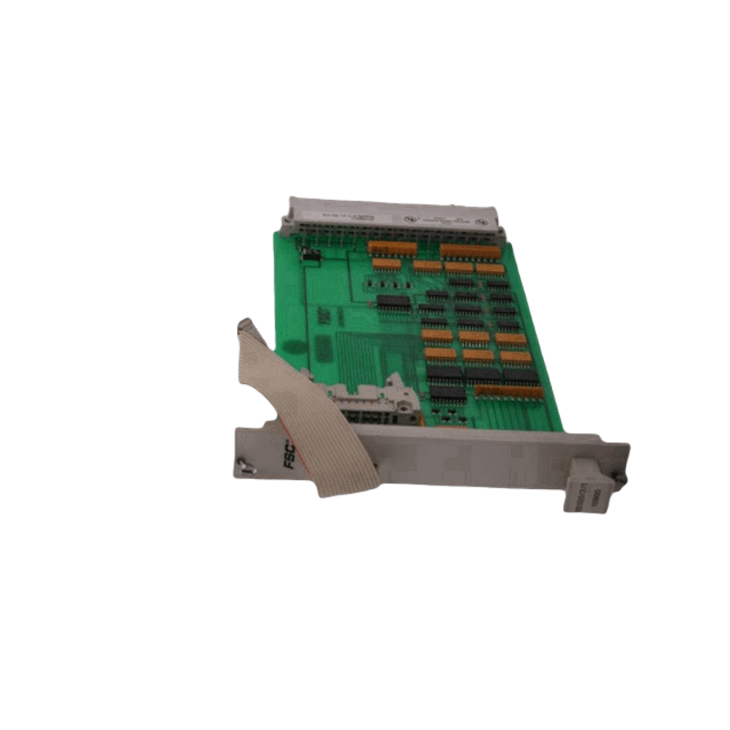
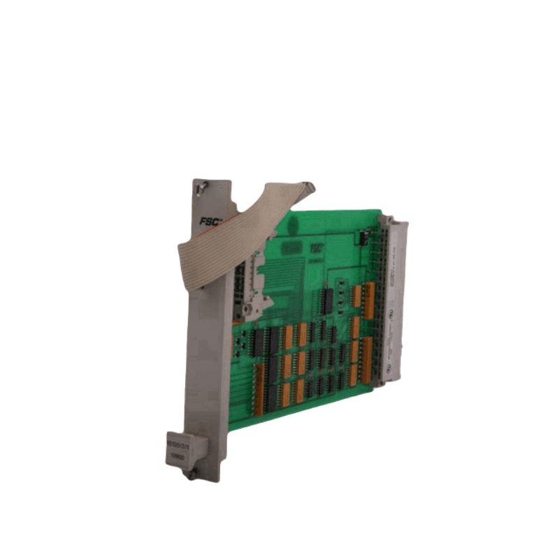
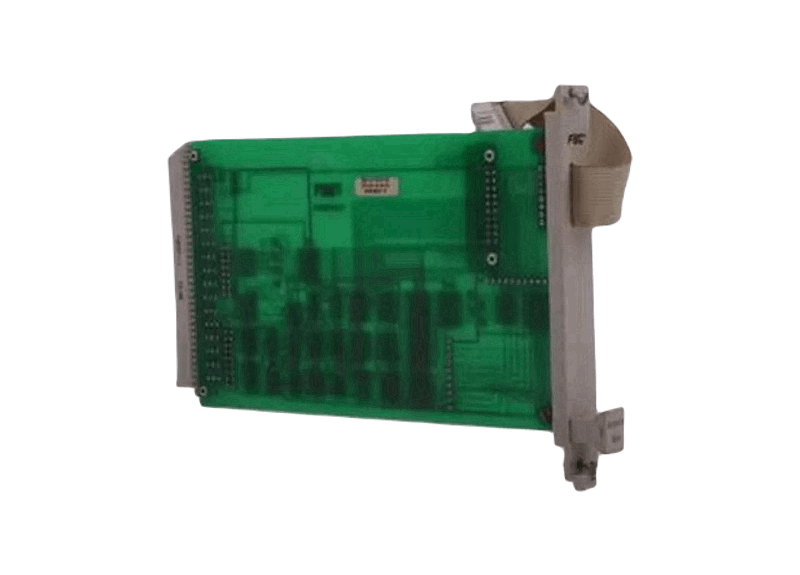
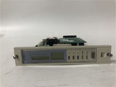
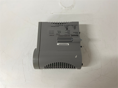
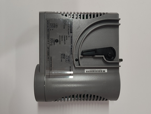
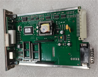
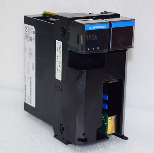
Honeywell 10100/2/1 Horizontal Bus Driver (HBD) Module
Manufacturer: Honeywell
Product No.: 10100/2/1
Condition: Brand new and in stock
Product Type: Horizontal bus driver module
Product Origin: USA
Payment: T/T, Western Union
Dimensions: 4 TE x 3 HE (= 4 HP x 3 U)
Weight: 0.11 kg
Certificate: CE, RoHS
Warranty: 12 months
Product Description
The horizontal bus driver (HBD) module is a basic module which is installed in the I/O racks.
The horizontal bus driver consists of two parts:
• electronic part (10100/2/1), and
• a A1, A21 or A22 flatcable.
The vertical bus flatcable between the Central Part and the I/O rack is connected to the HBD module via the back connector CN1 (see Figure 2).
The flatcable which extends from the front of the module connects the HBD module to the horizontal bus above the I/O rack.
The address selection lines of the I/O modules terminate on the back of the horizontal bus(es) via a flatcable on connector CN3.
The HBDs are used as follows:
− 10100/2/1 with flatcable A1 used for non-redundant I/O
− 10100/2/1 with flatcable A21 used for redundant I/O
(one rack per HBD)
− 10100/2/1 with flatcable A22 used for redundant I/O
(two racks per HBD)
The HBD may be replaced with the power switched on, but the Central Part will shut down if the HBD is safety-related.
Pin allocation
The HBD is fitted with a male connector according to DIN 41612 type F, with the ‘d’, ‘b’ and ‘z’ rows used.
The back view of the 10100/2/1 rack connector is as follows:
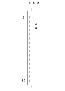
Figure 1 Back view of 10100/2/1 connector
Address setting
The rack address of the HBD is programmed by means of jumpers on the 10314/1/1, 10315/1/1, 10316/1/1 or 10317/1/1 modules (RA0 to RA3).
Table 1 Address setting for HBD
| RA3 | RA2 | RA1 | RA0 | |
| HBD1 | 0 | 0 | 0 | 1 |
| HBD2 | 0 | 0 | 1 | 0 |
| HBD3 | 0 | 0 | 1 | 1 |
| HBD4 | 0 | 1 | 0 | 0 |
| HBD5 | 0 | 1 | 0 | 1 |
| HBD6 | 0 | 1 | 1 | 0 |
| HBD7 | 1 | 0 | 0 | 0 |
| HBD8 | 1 | 0 | 0 | 1 |
| HBD9 | 1 | 0 | 1 | 0 |
| HBD10 | 1 | 1 | 0 | 0 |
0 = GND 5 Vdc 1 = Supply 5 Vdc
Flatcable routing
Figure 2 to Figure 4 below show the flatcable routing for the various configurations.
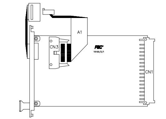
Figure 2 Schematic diagram for flatcable routing from the HBD (non-redundant I/O)
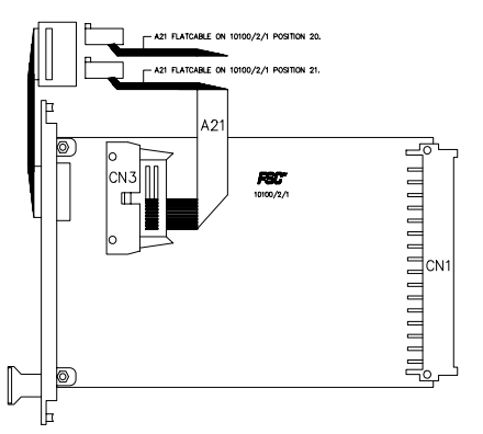
Figure 3 Schematic diagram for flatcable routing from the HBD
(redundant I/O with one rack per HBD)
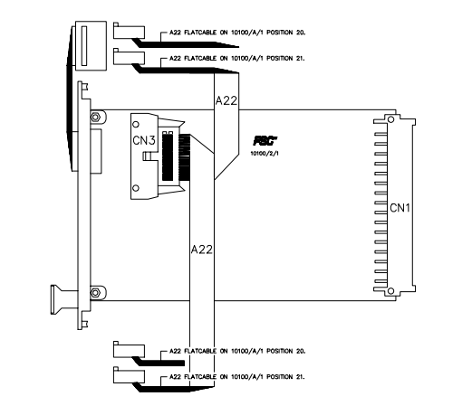
Figure 4 Schematic diagram for flatcable routing from the HBD
(redundant I/O with two racks per HBD)
Technical data
The 10100/2/1 module has the following specifications:
General
- Type number: 10100/2/1 10900
- Approvals: CE, TÜV, UL
- Software versions: ≥ 3.00
- Space requirements: 4 TE, 3 HE (= 4 HP, 3U)
Power
Power requirements:
- 10100/2/1 + A1 cable 5 Vdc 35 mA
- 10100/2/1 + A21 cable 5 Vdc 35 mA
- 10100/2/1 + A22 cable 5 Vdc 65 mA
Key coding
(See ‘Key coding’ data sheet)
Module code:
− holes A5, A7
Rack code:
− large pins A5, A7
More information about the 10100/2/1modules is available for download or online viewing in PDF format :3-4-6-10-14
 Loading comments...
Honeywell 10100/2/1 Horizontal Bus Driver (HBD) Module
Manufacturer: Honeywell
Product No.: 10100/2/1
Condition: Brand new and in stock
Product Type: Horizontal bus driver module
Product Origin: USA
Payment: T/T, Western Union
Dimensions: 4 TE x 3 HE (= 4 HP x 3 U)
Weight: 0.11 kg
Certificate: CE, RoHS
Warranty: 12 months
Product Description
The horizontal bus driver (HBD) module is a basic module which is installed in the I/O racks.
The horizontal bus driver consists of two parts:
• electronic part (10100/2/1), and
• a A1, A21 or A22 flatcable.
The vertical bus flatcable between the Central Part and the I/O rack is connected to the HBD module via the back connector CN1 (see Figure 2).
The flatcable which extends from the front of the module connects the HBD module to the horizontal bus above the I/O rack.
The address selection lines of the I/O modules terminate on the back of the horizontal bus(es) via a flatcable on connector CN3.
The HBDs are used as follows:
− 10100/2/1 with flatcable A1 used for non-redundant I/O
− 10100/2/1 with flatcable A21 used for redundant I/O
(one rack per HBD)
− 10100/2/1 with flatcable A22 used for redundant I/O
(two racks per HBD)
The HBD may be replaced with the power switched on, but the Central Part will shut down if the HBD is safety-related.
Pin allocation
The HBD is fitted with a male connector according to DIN 41612 type F, with the ‘d’, ‘b’ and ‘z’ rows used.
The back view of the 10100/2/1 rack connector is as follows:
Figure 1 Back view of 10100/2/1 connector
Address setting
The rack address of the HBD is programmed by means of jumpers on the 10314/1/1, 10315/1/1, 10316/1/1 or 10317/1/1 modules (RA0 to RA3).
Table 1 Address setting for HBD
| RA3 | RA2 | RA1 | RA0 | |
| HBD1 | 0 | 0 | 0 | 1 |
| HBD2 | 0 | 0 | 1 | 0 |
| HBD3 | 0 | 0 | 1 | 1 |
| HBD4 | 0 | 1 | 0 | 0 |
| HBD5 | 0 | 1 | 0 | 1 |
| HBD6 | 0 | 1 | 1 | 0 |
| HBD7 | 1 | 0 | 0 | 0 |
| HBD8 | 1 | 0 | 0 | 1 |
| HBD9 | 1 | 0 | 1 | 0 |
| HBD10 | 1 | 1 | 0 | 0 |
0 = GND 5 Vdc 1 = Supply 5 Vdc
Flatcable routing
Figure 2 to Figure 4 below show the flatcable routing for the various configurations.
Figure 2 Schematic diagram for flatcable routing from the HBD (non-redundant I/O)
Figure 3 Schematic diagram for flatcable routing from the HBD
(redundant I/O with one rack per HBD)
Figure 4 Schematic diagram for flatcable routing from the HBD
(redundant I/O with two racks per HBD)
Technical data
The 10100/2/1 module has the following specifications:
General
- Type number: 10100/2/1 10900
- Approvals: CE, TÜV, UL
- Software versions: ≥ 3.00
- Space requirements: 4 TE, 3 HE (= 4 HP, 3U)
Power
Power requirements:
- 10100/2/1 + A1 cable 5 Vdc 35 mA
- 10100/2/1 + A21 cable 5 Vdc 35 mA
- 10100/2/1 + A22 cable 5 Vdc 65 mA
Key coding
(See ‘Key coding’ data sheet)
Module code:
− holes A5, A7
Rack code:
− large pins A5, A7
More information about the 10100/2/1modules is available for download or online viewing in PDF format :3-4-6-10-14
Need a Custom Automation Solution?
Our team of experts can design and implement a tailored automation system to meet your specific requirements.