Our Products
Comprehensive industrial automation solutions for global industries
Contact us
If you are interested in our products and want to know more details,please Contact us,we will reply you as soon as we can.
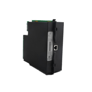
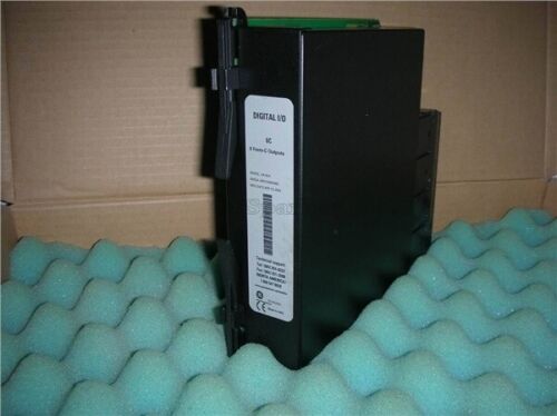
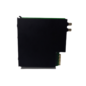
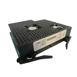
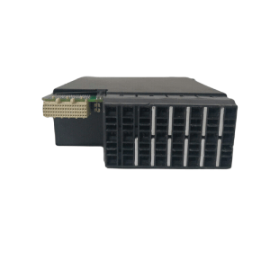

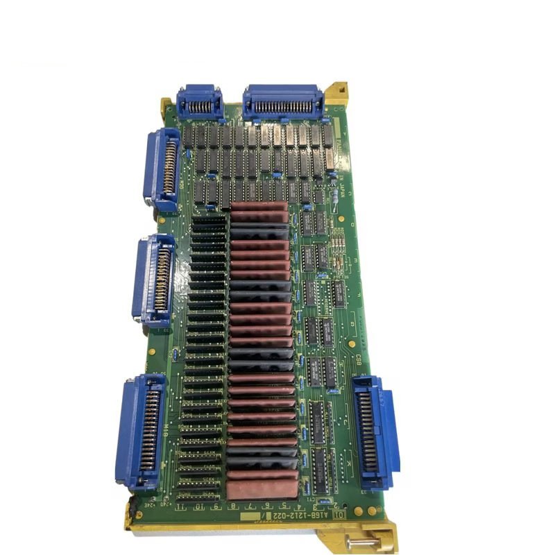
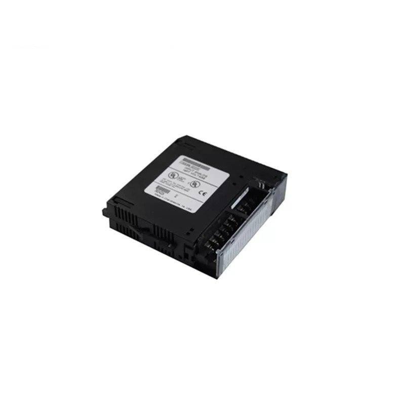
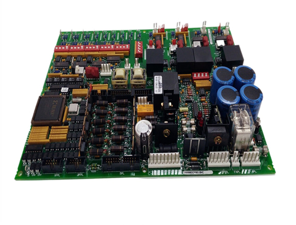
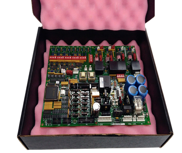
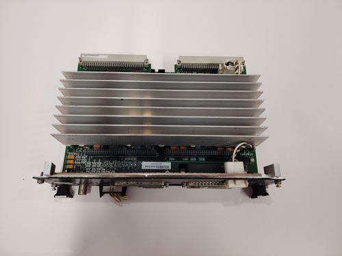
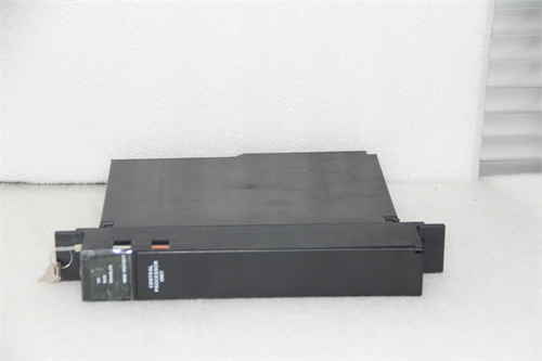
General Electric DS200DCFBG1BNC Voltage And Current Dual Loop Control
Module Number:DS200DCFBG1BNC
Product status:Discontinued
Delivery time:In stock
Product status:100% new
Sales country:All over the world
Product situation:one year warranty
Product Description
The control concept of DS200DCFBG1BNC is: UC3875 outputs 4 PWM pulses and controls VT1 to VT4 in the main circuit through the driving circuit. The output DC bus voltage is compared with the internal standard signal of UC3875 through the signal acquisition circuit, and the phase difference of the four PWM output pulses is adjusted to stabilize the output. After the input current passes through the signal acquisition circuit, it is compared with the overcurrent protection signal threshold inside UC3875. Once overcurrent occurs, UC3875 locks and trips, and DC/DC stops working, completing the input overcurrent protection.
Due to the significant difference in the state of the DS200DCFBG1BNC system when the inverter system operates in independent and grid connected modes, two different control methods are required.
When the inverter operates independently, voltage control mode is adopted, and the control block diagram is shown in Figure 3a. The control idea is: after sampling feedback, uo is compared with the sine wave reference voltage signal uref, the error signal is adjusted by PI, and then the corresponding driving signal is generated by the SPWM generator, which is sent to the main circuit to drive the switching transistor. The system transfer function can be obtained from the control block diagram as follows:
According to control theory, DS200DCFBG1BNC requires sufficient gain in the low frequency range to improve the stability performance of a closed-loop system; The mid frequency band should cross the horizontal axis at -20 dB/dec to ensure sufficient phase margin; The high-frequency range needs to be rapidly lowered to improve anti-interference ability.
 Loading comments...
General Electric DS200DCFBG1BNC Voltage And Current Dual Loop Control
Module Number:DS200DCFBG1BNC
Product status:Discontinued
Delivery time:In stock
Product status:100% new
Sales country:All over the world
Product situation:one year warranty
Product Description
The control concept of DS200DCFBG1BNC is: UC3875 outputs 4 PWM pulses and controls VT1 to VT4 in the main circuit through the driving circuit. The output DC bus voltage is compared with the internal standard signal of UC3875 through the signal acquisition circuit, and the phase difference of the four PWM output pulses is adjusted to stabilize the output. After the input current passes through the signal acquisition circuit, it is compared with the overcurrent protection signal threshold inside UC3875. Once overcurrent occurs, UC3875 locks and trips, and DC/DC stops working, completing the input overcurrent protection.
Due to the significant difference in the state of the DS200DCFBG1BNC system when the inverter system operates in independent and grid connected modes, two different control methods are required.
When the inverter operates independently, voltage control mode is adopted, and the control block diagram is shown in Figure 3a. The control idea is: after sampling feedback, uo is compared with the sine wave reference voltage signal uref, the error signal is adjusted by PI, and then the corresponding driving signal is generated by the SPWM generator, which is sent to the main circuit to drive the switching transistor. The system transfer function can be obtained from the control block diagram as follows:
According to control theory, DS200DCFBG1BNC requires sufficient gain in the low frequency range to improve the stability performance of a closed-loop system; The mid frequency band should cross the horizontal axis at -20 dB/dec to ensure sufficient phase margin; The high-frequency range needs to be rapidly lowered to improve anti-interference ability.
Need a Custom Automation Solution?
Our team of experts can design and implement a tailored automation system to meet your specific requirements.