Our Products
Comprehensive industrial automation solutions for global industries
Contact us
If you are interested in our products and want to know more details,please Contact us,we will reply you as soon as we can.
GE DS200DTBDG1ABB Printed Circuit Board
Manufacturer: GE
Product Number: DS200DTBDG1ABB
Category: Printed Circuit Board (Mark V Speedtronic)
Function: Industrial control circuit board for turbine systems
System Compatibility: GE Speedtronic Mark V turbine control
Application: Gas/steam turbine control, industrial automation
Product Description
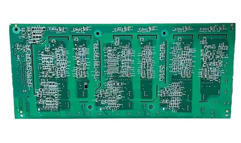
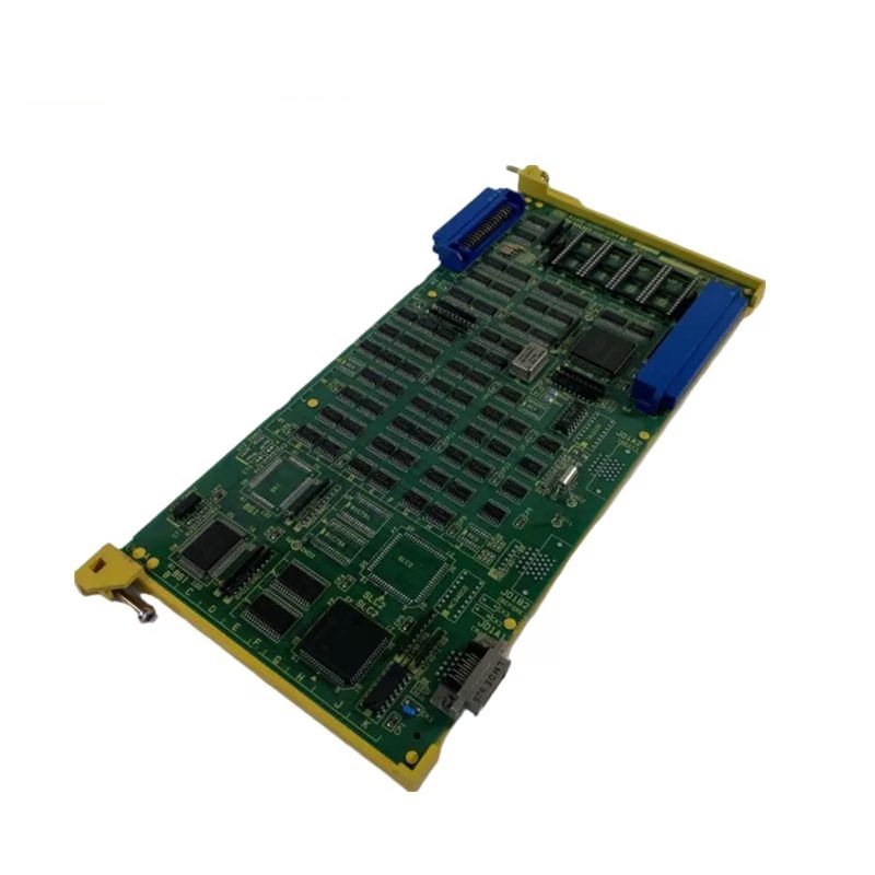
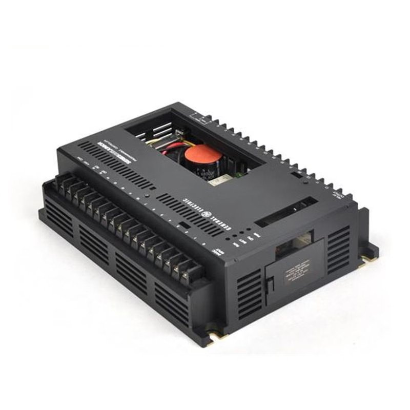
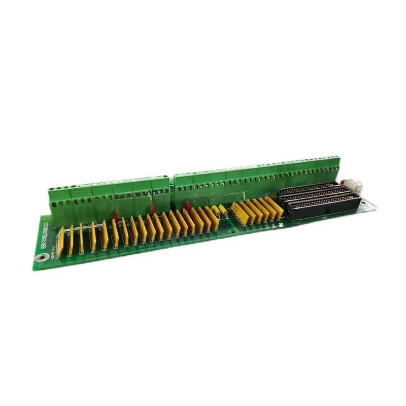
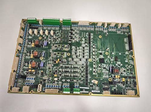
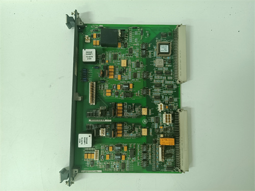
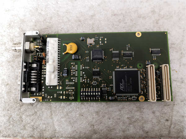
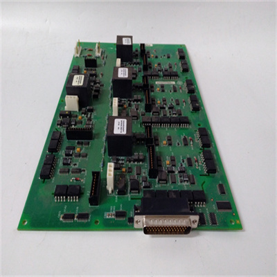
The DS200DTBDG1ABB is a specialized printed circuit board (PCB) essential to the legacy GE Mark V Turbine Control System Series. Designed for demanding wind, gas, and steam turbine environments, this PCB represents a final iteration of GE’s patented Speedtronic control technology. Known as the Contact Output Expansion Termination Module, it plays a critical role in enhancing system connectivity and reliability.
Type
- Specialized PCB for GE Mark V Turbine Control Systems
- Contact Output Expansion Termination Module
Features
- Expanded Connectivity: Increased contact output capacity compared to its predecessor, the DS200DTBDG1 module.
- Robust Construction: Built to withstand harsh conditions in turbine control systems.
- Seamless Integration: Compatible with other components within the Mark V ecosystem.
- Standard Hardware: Utilizes common Mark V Series components for reliability and maintainability.
Technical Specifications
- Connectors:
- JS1-JS8: TCRA Board Relay Signal Connectors
- J8: TCPD Board Solenoid Power Connector
- J19 and J20: Daisy-Chained Contact Outputs Power Connectors
- Components:
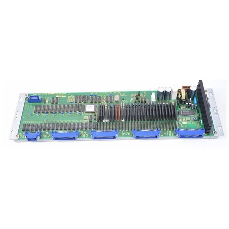
- Terminal Blocks: Two blocks with 107 terminals each
- Test Points: Multiple for easy diagnostics
- Jumpers: Two for configuration flexibility
- Connectors: Three 34-pin and three 40-pin connectors
- Voltage-Limiting Components: Standard Mark V Series rectifiers, diodes, capacitors
- Protective Coating: Ensures durability and performance in harsh environments
Installation Guidelines
- Preparation: Remove screws securing the PCB. Disconnect signal wires, ribbon cables, and other connections.
- Removal: Gently extract the PCB, avoiding contact with other components.
- Installation: Align the PCB accurately. Securely fasten it with screws. Reconnect cables, ensuring proper routing to avoid obstructing air vents.
- Caution: Handle components with care to prevent damage.
 Loading comments...
GE DS200DTBDG1ABB Printed Circuit Board
Manufacturer: GE
Product Number: DS200DTBDG1ABB
Category: Printed Circuit Board (Mark V Speedtronic)
Function: Industrial control circuit board for turbine systems
System Compatibility: GE Speedtronic Mark V turbine control
Application: Gas/steam turbine control, industrial automation
Product Description
The DS200DTBDG1ABB is a specialized printed circuit board (PCB) essential to the legacy GE Mark V Turbine Control System Series. Designed for demanding wind, gas, and steam turbine environments, this PCB represents a final iteration of GE’s patented Speedtronic control technology. Known as the Contact Output Expansion Termination Module, it plays a critical role in enhancing system connectivity and reliability.
Type
- Specialized PCB for GE Mark V Turbine Control Systems
- Contact Output Expansion Termination Module
Features
- Expanded Connectivity: Increased contact output capacity compared to its predecessor, the DS200DTBDG1 module.
- Robust Construction: Built to withstand harsh conditions in turbine control systems.
- Seamless Integration: Compatible with other components within the Mark V ecosystem.
- Standard Hardware: Utilizes common Mark V Series components for reliability and maintainability.
Technical Specifications
- Connectors:
- JS1-JS8: TCRA Board Relay Signal Connectors
- J8: TCPD Board Solenoid Power Connector
- J19 and J20: Daisy-Chained Contact Outputs Power Connectors
- Components:
- Terminal Blocks: Two blocks with 107 terminals each
- Test Points: Multiple for easy diagnostics
- Jumpers: Two for configuration flexibility
- Connectors: Three 34-pin and three 40-pin connectors
- Voltage-Limiting Components: Standard Mark V Series rectifiers, diodes, capacitors
- Protective Coating: Ensures durability and performance in harsh environments
Installation Guidelines
- Preparation: Remove screws securing the PCB. Disconnect signal wires, ribbon cables, and other connections.
- Removal: Gently extract the PCB, avoiding contact with other components.
- Installation: Align the PCB accurately. Securely fasten it with screws. Reconnect cables, ensuring proper routing to avoid obstructing air vents.
- Caution: Handle components with care to prevent damage.
Need a Custom Automation Solution?
Our team of experts can design and implement a tailored automation system to meet your specific requirements.