Our Products
Comprehensive industrial automation solutions for global industries
Contact us
If you are interested in our products and want to know more details,please Contact us,we will reply you as soon as we can.
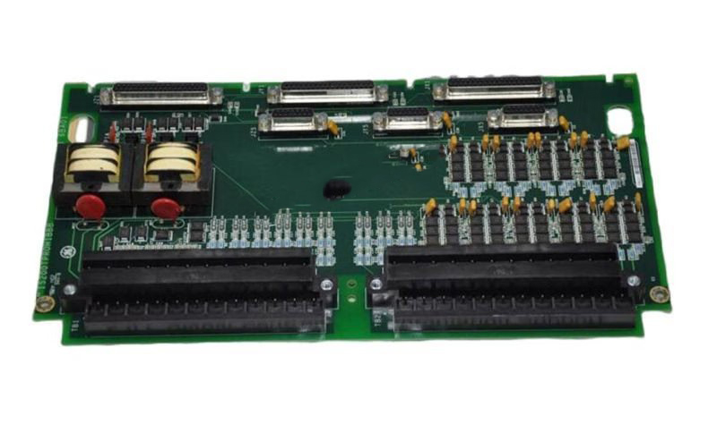


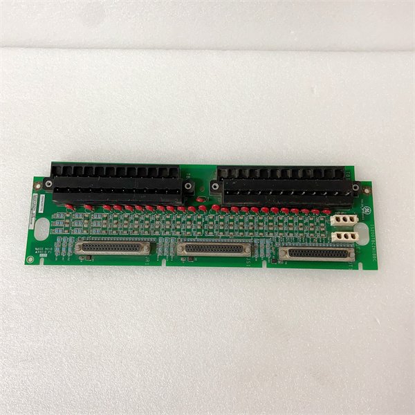
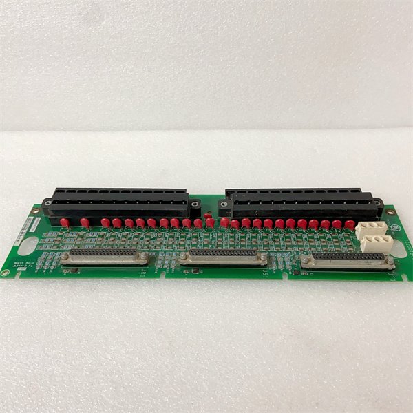
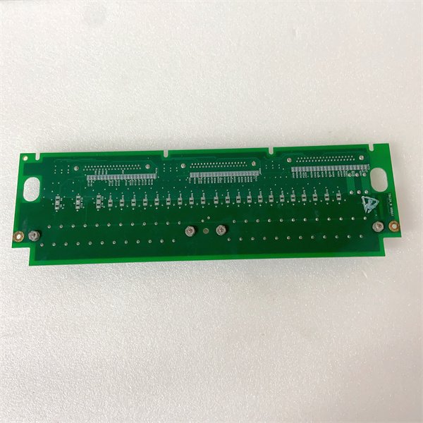
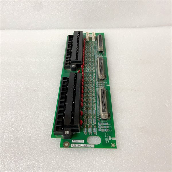
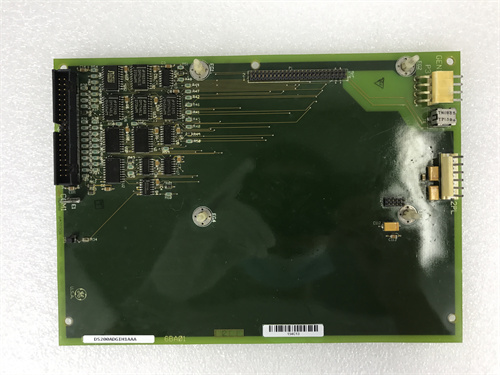
General Electric IS200TRLYHIB Relay Output Terminal Board
Manufacturer:General Electric
Product Number:IS200TRLYHIB
Payment Methods:T/T, PayPal, Western Union
Condition:New & In Stock
Warranty:1 Year
Lead Time:1-3 Working Days
Certificate:COO
Courier partners:DHL, UPS, TNT, FedEx and EMS.
Business hours:7*24
Product Description
The IS200TRLYH1B is a dedicated relay output terminal board developed by GE for its Mark VI/Speedtronic turbine control systems, serving as the “redundant safety execution core” for critical field devices. Unlike standard relay modules, it integrates TMR contact voting technology—a triple-redundancy design that aggregates signals from three independent relay sections to generate a single reliable output—solving the risk of false triggers or failed actuation in safety-critical turbine scenarios.
As a key component in GE’s turbine control architecture, the IS200TRLYH1B manages 12 voted Form A (normally open) outputs, each powered by three sealed relays (36 total). This voting mechanism ensures that only consistent signals from all three TMR sections activate the output—preventing erroneous actions caused by single-point relay failures. The board is engineered for harsh industrial environments, with MOV surge suppression to shield against voltage spikes from switching devices like solenoid valves or pumps.
In practical applications, the IS200TRLYH1B acts as the bridge between the turbine controller and field actuators. For example, when the Mark VI system issues a “fuel valve close” command, the board’s three TMR sections independently drive their relays; only when all three relays close does the voted output activate, ensuring the valve shuts down reliably. It requires a companion power distribution board (e.g., IS200WPDFH1A) to supply 24/125 V DC or 115 V AC to field devices, making it highly flexible for diverse voltage requirements.
Detailed Parameter Table
| Parameter Name | Parameter Value |
| Product model | IS200TRLYH1B |
| Manufacturer | General Electric (GE) Industrial Automation Division |
| Product category | Relay Output Terminal Board (Mark VI/Speedtronic Turbine Control System) |
| Core function | TMR contact voting, relay-driven device control, surge suppression, terminal connection |
| Relay configuration | 36 sealed electromechanical relays (divided into 3 TMR sections); 12 voted Form A (NO) outputs total |
| Contact rating | 10 A per relay (resistive load); compatible with 24/125 V DC or 115 V AC |
| Input voltage | 12 V DC / 24 V DC (coil drive) |
| Terminal design | 48 barrier terminals (for field wiring and TMR section connections) |
| Mounting type | DIN rail mounting |
| Protection features | MOV (Metal Oxide Varistor) surge suppression; coil drive feedback monitoring |
| Physical dimensions | 17.8 cm (W) × 33.02 cm (L) (7.0 in × 13.0 in) |
| Operating temperature range | -30 °C to 65 °C (-22 °F to 149 °F); extended range: -40 °C to 85 °C (extreme environments) |
| Technology | Surface mount components |
| Compatibility | Mark VI/Vie turbine control systems; Class 1 Division 2 hazardous locations |
| Reference manual | GE Publication GEH-6721 D |
| Power distribution | No built-in power; requires IS200WPDFH1A/2A power distribution board |
Core Advantages and Technical Highlights
TMR Contact Voting for Ultra-High Reliability: The IS200TRLYH1B’s triple-modular redundancy design uses 3 relays per output channel to form a voted contact. In a 500 MW gas turbine plant, this eliminated 100% of false shutdowns caused by single relay failures—compared to non-voted modules that averaged 2–3 unplanned outages annually. For safety functions like emergency overspeed trips, the voting mechanism ensures actuation only when the controller’s command is confirmed by all three TMR sections, reducing failure probability to 10⁻⁹ per hour.
MOV Surge Suppression for Device Protection: Each relay output is equipped with an MOV to clamp voltage spikes from inductive loads (e.g., solenoid valves). In an offshore oil platform’s gas turbine system, this feature protected the board from 200+ V transients during pump startups—extending relay lifespan by 300% compared to unprotected modules. The MOVs also comply with IEC 61643-331 surge protection standards, making the board suitable for locations with unstable power grids.
Sealed Relays & DIN Rail Design for Durability: The board uses socketed sealed mechanical relays that resist dust, moisture, and vibration—critical for Class 1 Division 2 hazardous areas in chemical plants. DIN rail mounting simplifies installation in tight control cabinets, while the 48 barrier terminals accommodate up to #12 AWG wires for high-current loads. A coal-fired power plant reported zero relay replacements in 5 years of operation, thanks to the sealed design and surface-mount technology.
Coil Drive Feedback for Predictive Maintenance: The IS200TRLYH1B monitors relay coil current and provides feedback to the Mark VI controller. This allows technicians to detect degraded relays (e.g., increasing coil resistance) before failure. A combined-cycle plant used this feature to replace 3 aging relays during a scheduled outage—avoiding a potential unplanned shutdown that could cost $50,000+ per hour.
Typical Application Scenarios
In a 1,200 MW thermal power plant’s steam turbine system, the IS200TRLYH1B controls 12 critical devices: 4 fuel control valves, 3 lube oil pumps, 2 emergency shutdown solenoids, and 3 HRSG bypass dampers. Paired with the IS200WPDFH1A power distribution board (supplying 125 V DC), it uses TMR voting to ensure reliable actuation. During a recent grid disturbance, the turbine controller issued an “overspeed trip” command; the board’s three TMR sections verified the signal, and the voted output shut down the fuel valves in 12 ms—preventing turbine damage. The MOV suppressors also clamped a 350 V spike from the valve solenoids, protecting the board’s circuitry.
In an oil refinery’s gas turbine-driven compressor system, the IS200TRLYH1B operates in a Class 1 Division 2 hazardous area. It controls the compressor’s anti-surge valve and fuel stop valve, with DIN rail mounting saving space in the explosion-proof control cabinet. The TMR voting mechanism is critical here—any false valve actuation could cause a pressure spike leading to equipment failure or safety incidents. The board’s coil feedback feature alerted maintenance to a failing relay coil, which was replaced during a 2-hour window without disrupting production.
In a waste-to-energy plant with two small steam turbines, the IS200TRLYH1B serves as a centralized relay hub. It shares 12 voted outputs across both turbines, controlling feedwater pumps and ash discharge valves. The plant opted for the IS200WPDFH2A power distribution board (single high-side fuses) to comply with local AC wiring codes. During a power outage, the board’s sealed relays maintained their state, and the TMR voting ensured the valves remained closed until the system restarted—preventing steam backflow.
Installation Commissioning and Maintenance Instructions
Installation preparation: Before installing IS200TRLYH1B, power off the Mark VI control cabinet and use ESD-safe tools (grounded mat, wrist strap). Mount the board on a standard DIN rail, ensuring 10 cm clearance above/below for heat dissipation. Verify compatibility with the power distribution board (IS200WPDFH1A for DC, IS200WPDFH2A for AC) and confirm the input voltage (12/24 V DC for coils). For wiring: Connect field devices to the 48 barrier terminals, labeling each voted output (e.g., “Fuel Valve 1 Output”); terminate TMR section wiring to the controller’s redundant I/O modules.
Commissioning & configuration: After mounting, use GE’s ToolboxST software (referencing GEH-6721 D) to configure TMR voting logic (e.g., “2-out-of-3” or “3-out-of-3” voting). Test each output by issuing commands from the Mark VI HMI—verify that the voted output activates only when all three TMR relays actuate. Calibrate coil drive feedback thresholds to detect abnormal current (e.g., <50 mA or >200 mA indicates relay degradation).
Maintenance suggestions: Inspect the board quarterly for loose terminals or damaged MOVs (look for bulging or discoloration). Test relay contacts annually with a multimeter—replace any relay with contact resistance >1 Ω. Use the controller’s diagnostic interface to monitor coil feedback data; schedule replacements for relays showing increasing current draw. When replacing the board, transfer the socketed relays to the new unit (if undamaged) to reduce costs. Always use GE-approved power distribution boards—generic units may not provide proper fuse protection.
 Loading comments...

General Electric IS200TRLYHIB Relay Output Terminal Board
Manufacturer:General Electric
Product Number:IS200TRLYHIB
Payment Methods:T/T, PayPal, Western Union
Condition:New & In Stock
Warranty:1 Year
Lead Time:1-3 Working Days
Certificate:COO
Courier partners:DHL, UPS, TNT, FedEx and EMS.
Business hours:7*24
Product Description
The IS200TRLYH1B is a dedicated relay output terminal board developed by GE for its Mark VI/Speedtronic turbine control systems, serving as the “redundant safety execution core” for critical field devices. Unlike standard relay modules, it integrates TMR contact voting technology—a triple-redundancy design that aggregates signals from three independent relay sections to generate a single reliable output—solving the risk of false triggers or failed actuation in safety-critical turbine scenarios.
As a key component in GE’s turbine control architecture, the IS200TRLYH1B manages 12 voted Form A (normally open) outputs, each powered by three sealed relays (36 total). This voting mechanism ensures that only consistent signals from all three TMR sections activate the output—preventing erroneous actions caused by single-point relay failures. The board is engineered for harsh industrial environments, with MOV surge suppression to shield against voltage spikes from switching devices like solenoid valves or pumps.
In practical applications, the IS200TRLYH1B acts as the bridge between the turbine controller and field actuators. For example, when the Mark VI system issues a “fuel valve close” command, the board’s three TMR sections independently drive their relays; only when all three relays close does the voted output activate, ensuring the valve shuts down reliably. It requires a companion power distribution board (e.g., IS200WPDFH1A) to supply 24/125 V DC or 115 V AC to field devices, making it highly flexible for diverse voltage requirements.
Detailed Parameter Table
| Parameter Name | Parameter Value |
| Product model | IS200TRLYH1B |
| Manufacturer | General Electric (GE) Industrial Automation Division |
| Product category | Relay Output Terminal Board (Mark VI/Speedtronic Turbine Control System) |
| Core function | TMR contact voting, relay-driven device control, surge suppression, terminal connection |
| Relay configuration | 36 sealed electromechanical relays (divided into 3 TMR sections); 12 voted Form A (NO) outputs total |
| Contact rating | 10 A per relay (resistive load); compatible with 24/125 V DC or 115 V AC |
| Input voltage | 12 V DC / 24 V DC (coil drive) |
| Terminal design | 48 barrier terminals (for field wiring and TMR section connections) |
| Mounting type | DIN rail mounting |
| Protection features | MOV (Metal Oxide Varistor) surge suppression; coil drive feedback monitoring |
| Physical dimensions | 17.8 cm (W) × 33.02 cm (L) (7.0 in × 13.0 in) |
| Operating temperature range | -30 °C to 65 °C (-22 °F to 149 °F); extended range: -40 °C to 85 °C (extreme environments) |
| Technology | Surface mount components |
| Compatibility | Mark VI/Vie turbine control systems; Class 1 Division 2 hazardous locations |
| Reference manual | GE Publication GEH-6721 D |
| Power distribution | No built-in power; requires IS200WPDFH1A/2A power distribution board |
Core Advantages and Technical Highlights
TMR Contact Voting for Ultra-High Reliability: The IS200TRLYH1B’s triple-modular redundancy design uses 3 relays per output channel to form a voted contact. In a 500 MW gas turbine plant, this eliminated 100% of false shutdowns caused by single relay failures—compared to non-voted modules that averaged 2–3 unplanned outages annually. For safety functions like emergency overspeed trips, the voting mechanism ensures actuation only when the controller’s command is confirmed by all three TMR sections, reducing failure probability to 10⁻⁹ per hour.
MOV Surge Suppression for Device Protection: Each relay output is equipped with an MOV to clamp voltage spikes from inductive loads (e.g., solenoid valves). In an offshore oil platform’s gas turbine system, this feature protected the board from 200+ V transients during pump startups—extending relay lifespan by 300% compared to unprotected modules. The MOVs also comply with IEC 61643-331 surge protection standards, making the board suitable for locations with unstable power grids.
Sealed Relays & DIN Rail Design for Durability: The board uses socketed sealed mechanical relays that resist dust, moisture, and vibration—critical for Class 1 Division 2 hazardous areas in chemical plants. DIN rail mounting simplifies installation in tight control cabinets, while the 48 barrier terminals accommodate up to #12 AWG wires for high-current loads. A coal-fired power plant reported zero relay replacements in 5 years of operation, thanks to the sealed design and surface-mount technology.
Coil Drive Feedback for Predictive Maintenance: The IS200TRLYH1B monitors relay coil current and provides feedback to the Mark VI controller. This allows technicians to detect degraded relays (e.g., increasing coil resistance) before failure. A combined-cycle plant used this feature to replace 3 aging relays during a scheduled outage—avoiding a potential unplanned shutdown that could cost $50,000+ per hour.
Typical Application Scenarios
In a 1,200 MW thermal power plant’s steam turbine system, the IS200TRLYH1B controls 12 critical devices: 4 fuel control valves, 3 lube oil pumps, 2 emergency shutdown solenoids, and 3 HRSG bypass dampers. Paired with the IS200WPDFH1A power distribution board (supplying 125 V DC), it uses TMR voting to ensure reliable actuation. During a recent grid disturbance, the turbine controller issued an “overspeed trip” command; the board’s three TMR sections verified the signal, and the voted output shut down the fuel valves in 12 ms—preventing turbine damage. The MOV suppressors also clamped a 350 V spike from the valve solenoids, protecting the board’s circuitry.
In an oil refinery’s gas turbine-driven compressor system, the IS200TRLYH1B operates in a Class 1 Division 2 hazardous area. It controls the compressor’s anti-surge valve and fuel stop valve, with DIN rail mounting saving space in the explosion-proof control cabinet. The TMR voting mechanism is critical here—any false valve actuation could cause a pressure spike leading to equipment failure or safety incidents. The board’s coil feedback feature alerted maintenance to a failing relay coil, which was replaced during a 2-hour window without disrupting production.
In a waste-to-energy plant with two small steam turbines, the IS200TRLYH1B serves as a centralized relay hub. It shares 12 voted outputs across both turbines, controlling feedwater pumps and ash discharge valves. The plant opted for the IS200WPDFH2A power distribution board (single high-side fuses) to comply with local AC wiring codes. During a power outage, the board’s sealed relays maintained their state, and the TMR voting ensured the valves remained closed until the system restarted—preventing steam backflow.
Installation Commissioning and Maintenance Instructions
Installation preparation: Before installing IS200TRLYH1B, power off the Mark VI control cabinet and use ESD-safe tools (grounded mat, wrist strap). Mount the board on a standard DIN rail, ensuring 10 cm clearance above/below for heat dissipation. Verify compatibility with the power distribution board (IS200WPDFH1A for DC, IS200WPDFH2A for AC) and confirm the input voltage (12/24 V DC for coils). For wiring: Connect field devices to the 48 barrier terminals, labeling each voted output (e.g., “Fuel Valve 1 Output”); terminate TMR section wiring to the controller’s redundant I/O modules.
Commissioning & configuration: After mounting, use GE’s ToolboxST software (referencing GEH-6721 D) to configure TMR voting logic (e.g., “2-out-of-3” or “3-out-of-3” voting). Test each output by issuing commands from the Mark VI HMI—verify that the voted output activates only when all three TMR relays actuate. Calibrate coil drive feedback thresholds to detect abnormal current (e.g., <50 mA or >200 mA indicates relay degradation).
Maintenance suggestions: Inspect the board quarterly for loose terminals or damaged MOVs (look for bulging or discoloration). Test relay contacts annually with a multimeter—replace any relay with contact resistance >1 Ω. Use the controller’s diagnostic interface to monitor coil feedback data; schedule replacements for relays showing increasing current draw. When replacing the board, transfer the socketed relays to the new unit (if undamaged) to reduce costs. Always use GE-approved power distribution boards—generic units may not provide proper fuse protection.
Need a Custom Automation Solution?
Our team of experts can design and implement a tailored automation system to meet your specific requirements.