Our Products
Comprehensive industrial automation solutions for global industries
Contact us
If you are interested in our products and want to know more details,please Contact us,we will reply you as soon as we can.

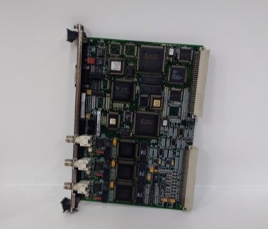
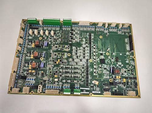
General Electric IS200TRLYH1C Entry-to-Mid-Range Relay Output Terminal Board
Manufacturer:General Electric
Product Number:IS200TRLYH1C
Payment Methods:T/T, PayPal, Western Union
Condition:New & In Stock
Warranty:1 Year
Lead Time:1-3 Working Days
Certificate:COO
Courier partners:DHL, UPS, TNT, FedEx and EMS.
Business hours:7*24
Product Description
The IS200TRLYH1C is GE’s entry-to-mid-range relay output terminal board, engineered for Mark VI/Speedtronic turbine control systems to serve as a reliable, cost-effective upgrade from the foundational IS200TRLYH1B. It retains the 3-section TMR redundancy that makes GE’s relay boards trusted for safety-critical tasks—such as fuel valve control and emergency shutdowns—while adding key improvements: broader voltage compatibility (250 V DC/230 V AC vs. 125 V DC/115 V AC in 1B), reinforced terminals, and enhanced surge protection. These upgrades make it ideal for small-to-medium turbines (30–150 MW) in industrial plants, small power stations, or retrofits of older Mark VI systems.
Unlike the IS200TRLYH1B, IS200TRLYH1C eliminates the need for external voltage converters when controlling 230 V AC devices (e.g., small cooling fans) or 250 V DC actuators (e.g., hydraulic valves)—simplifying wiring and reducing points of failure. Its reinforced screw terminals (tin-plated for corrosion resistance) also address the 1B model’s occasional terminal wear in high-vibration environments, such as reciprocating gas turbines.
In GE’s automation ecosystem, IS200TRLYH1C acts as a “no-frills safety layer” between the turbine controller and field devices. For example, when the Mark VI system detects a low lube oil pressure, the board’s 3 TMR sections independently validate the “pump start” command; only when all three sections agree does the Form A output activate, ensuring the pump runs without false triggers. On-board LEDs for each TMR section let technicians quickly identify failed sections during maintenance, avoiding time-consuming HMI checks.
Detailed Parameter Table
| Parameter Name | Parameter Value |
| Product model | IS200TRLYH1C |
| Manufacturer | General Electric (GE) Industrial Automation Division |
| Product category | Entry-to-Mid-Range Relay Output Terminal Board (Mark VI/Speedtronic System) |
| Core function | 3-section TMR voting, fixed Form A outputs, medium-current control, upgraded surge protection |
| Relay configuration | 36 sealed electromechanical relays (3 TMR sections); 12 fixed Form A (NO) outputs |
| Contact rating | 11 A per relay (resistive load); 5.5 A (inductive load); 24/125/250 V DC or 115/230 V AC |
| Input voltage | 24 V DC (coil drive); single power input with optional backup terminal |
| Terminal design | 48 reinforced screw terminals (torque range: 0.4–0.8 N·m); compatible with #12–22 AWG wires |
| Mounting type | DIN rail mounting (35 mm standard rails); direct panel mounting holes included |
| Protection features | Enhanced MOV surge suppression (1.1 kV clamping voltage); 5 A cartridge fuses per TMR section |
| Diagnostic capabilities | Coil current monitoring (via Mark VI HMI); TMR section fault LEDs (on-board) |
| Physical dimensions | 17.8 cm (W) × 33.0 cm (L) (7.0 in × 13.0 in) |
| Operating temperature range | -30 °C to 70 °C (-22 °F to 158 °F); derated to 60 °C at max current |
| Technology | Surface mount components; RoHS compliant; tin-plated terminal contacts |
| Compatibility | Mark VI/Vie systems; Class 1 Division 2 hazardous locations (limited approval) |
| Reference manual | GE Publication GEH-6721 B |
| Power distribution |
Requires IS200WPDFH1A (single-power distribution board); no hot-swap support |
Core Advantages and Technical Highlights
Broader Voltage Compatibility for Global Use: IS200TRLYH1C supports 24/125/250 V DC and 115/230 V AC—an upgrade from the IS200TRLYH1B’s limited 125 V DC/115 V AC range. A small natural gas plant in Europe used this feature to control 115 V AC (pumps) and 230 V AC (fans) devices with a single board—replacing two IS200TRLYH1B units (one for each voltage) and cutting cabinet space by 50%. This global compatibility also simplifies inventory for multinational industrial companies, as one model works across regional sites.
Enhanced Surge Protection for Grid Stability: With a 1.1 kV clamping voltage MOV (vs. 1.0 kV in IS200TRLYH1B), IS200TRLYH1C better withstands voltage spikes from grid fluctuations or device switching. A food processing plant with a 50 MW steam turbine reported zero relay failures in 2 years—compared to 1–2 annual failures with the IS200TRLYH1B—during seasonal grid demand peaks. The 5 A cartridge fuses per TMR section also provide faster overcurrent protection than the 1B’s blade fuses, reducing relay damage from short circuits.
Reinforced Terminals for Durability: IS200TRLYH1C’s tin-plated, reinforced screw terminals resist corrosion and vibration-induced loosening—common issues with the IS200TRLYH1B in harsh industrial environments. A wastewater treatment plant with a 30 MW biogas turbine found terminal retightening frequency dropped from quarterly to annually, saving 8 hours of maintenance per year. The terminals also accept #12 AWG wires (vs. #14 max in 1B), supporting higher-current loads without wire overheating.
Cost-Effective TMR Redundancy: IS200TRLYH1C retains the 3-section TMR voting of the IS200TRLYH1B but adds upgrades without a significant price increase. A small coal-fired power plant in Asia chose it over more expensive models (e.g., IS200TRLYH2C) for its 80 MW turbine, as the 3-section voting met safety requirements while the voltage and terminal upgrades solved their specific pain points. This balance of performance and cost makes it a top choice for budget-constrained projects.
Typical Application Scenarios
In a 50 MW biomass-fired power plant’s steam turbine system, IS200TRLYH1C controls 12 critical devices: 4 fuel feed valves (24 V DC, 8 A), 3 ash conveyor motors (115 V AC, 7 A), 3 cooling fans (230 V AC, 9 A), and 2 emergency shutdown solenoids (125 V DC, 3 A). Paired with the IS200WPDFH1A power board, its 3 TMR sections ensure reliable actuation. During a grid voltage spike (1.2x nominal) from a nearby factory, the enhanced MOV clamped the transient, protecting the relays. Later, a TMR section fault LED alerted technicians to a failed relay, which was replaced during a 1-hour maintenance window—avoiding unplanned downtime.
In a chemical plant’s 70 MW process steam turbine system (Class 1 Division 2, limited approval), IS200TRLYH1C operates in a moderately corrosive environment, controlling 8 process valve solenoids (24 V DC, 4 A) and 4 condensate pump starters (250 V DC, 10 A). Its tin-plated terminals prevented rust buildup (a problem with the IS200TRLYH1B), and the 11 A resistive rating handled the pumps without external contactors. The plant’s maintenance team valued the fixed Form A outputs—they aligned with the “fail-closed” safety logic of most process valves, eliminating the need for software configuration.
In a retrofitted 100 MW reciprocating gas turbine system (originally Mark VI), IS200TRLYH1C replaced aging IS200TRLYH1B boards. Its reinforced terminals withstood the turbine’s high vibration, and the broader voltage compatibility let the plant add 230 V AC auxiliary fans without rewiring. During commissioning, the on-board TMR LEDs simplified testing—technicians verified each section’s operation in 15 minutes, vs. 45 minutes with the IS200TRLYH1B’s single system LED.
Installation, Commissioning and Maintenance Instructions
Installation preparation: Before installing IS200TRLYH1C, power off the Mark VI cabinet and use ESD-safe tools. Mount on a 35 mm DIN rail (or direct panel mount via included holes) with 10 cm clearance above/below for heat (derate to 60 °C at 11 A). Connect the 24 V DC power input to IS200WPDFH1A; use the optional backup terminal (if needed) to connect a 24 V DC battery for power loss resilience. For wiring: Use #12 AWG wires for 11 A loads, #22 AWG for low-current devices; tighten terminals to 0.4–0.8 N·m (use a torque wrench to avoid over-tightening). Label each output (e.g., “Fuel Valve 3–Form A”) to avoid confusion.
Commissioning & configuration: Use GE’s ToolboxST software (GEH-6721 B) to set TMR voting logic (2-out-of-3 recommended). Calibrate coil current thresholds (85–115 mA for healthy relays). Test each output by issuing commands from the Mark VI HMI—confirm the Form A output activates (closes) when commanded and deactivates (opens) on power loss. Verify TMR section LEDs (green = normal, red = fault) by simulating a relay failure (disconnect one relay coil).
Maintenance suggestions: Inspect terminals quarterly—clean corrosion with a dry cloth and retighten to torque specs. Test relay contacts annually with a multimeter (replace if resistance >1 Ω). Monitor coil current via the HMI—alert if current drops below 80 mA or rises above 120 mA (indicates relay degradation). If a TMR section faults (red LED), power off the board, replace the affected GE CR4700 relays, and replace the 5 A cartridge fuse. Never use non-GE relays or fuses—they may not fit or meet safety ratings.
 Loading comments...
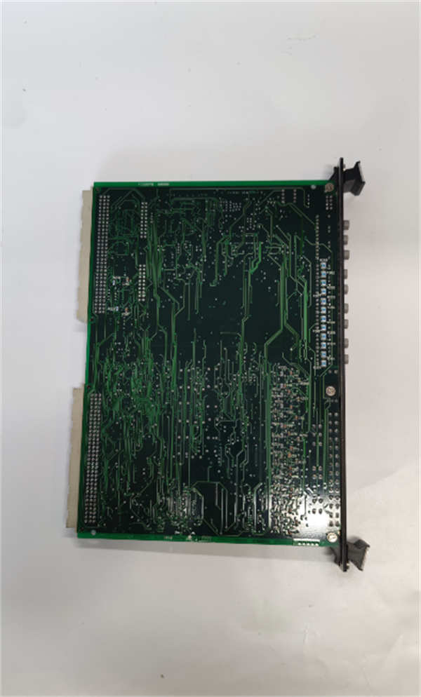

General Electric IS200TRLYH1C Entry-to-Mid-Range Relay Output Terminal Board
Manufacturer:General Electric
Product Number:IS200TRLYH1C
Payment Methods:T/T, PayPal, Western Union
Condition:New & In Stock
Warranty:1 Year
Lead Time:1-3 Working Days
Certificate:COO
Courier partners:DHL, UPS, TNT, FedEx and EMS.
Business hours:7*24
Product Description
The IS200TRLYH1C is GE’s entry-to-mid-range relay output terminal board, engineered for Mark VI/Speedtronic turbine control systems to serve as a reliable, cost-effective upgrade from the foundational IS200TRLYH1B. It retains the 3-section TMR redundancy that makes GE’s relay boards trusted for safety-critical tasks—such as fuel valve control and emergency shutdowns—while adding key improvements: broader voltage compatibility (250 V DC/230 V AC vs. 125 V DC/115 V AC in 1B), reinforced terminals, and enhanced surge protection. These upgrades make it ideal for small-to-medium turbines (30–150 MW) in industrial plants, small power stations, or retrofits of older Mark VI systems.
Unlike the IS200TRLYH1B, IS200TRLYH1C eliminates the need for external voltage converters when controlling 230 V AC devices (e.g., small cooling fans) or 250 V DC actuators (e.g., hydraulic valves)—simplifying wiring and reducing points of failure. Its reinforced screw terminals (tin-plated for corrosion resistance) also address the 1B model’s occasional terminal wear in high-vibration environments, such as reciprocating gas turbines.
In GE’s automation ecosystem, IS200TRLYH1C acts as a “no-frills safety layer” between the turbine controller and field devices. For example, when the Mark VI system detects a low lube oil pressure, the board’s 3 TMR sections independently validate the “pump start” command; only when all three sections agree does the Form A output activate, ensuring the pump runs without false triggers. On-board LEDs for each TMR section let technicians quickly identify failed sections during maintenance, avoiding time-consuming HMI checks.
Detailed Parameter Table
| Parameter Name | Parameter Value |
| Product model | IS200TRLYH1C |
| Manufacturer | General Electric (GE) Industrial Automation Division |
| Product category | Entry-to-Mid-Range Relay Output Terminal Board (Mark VI/Speedtronic System) |
| Core function | 3-section TMR voting, fixed Form A outputs, medium-current control, upgraded surge protection |
| Relay configuration | 36 sealed electromechanical relays (3 TMR sections); 12 fixed Form A (NO) outputs |
| Contact rating | 11 A per relay (resistive load); 5.5 A (inductive load); 24/125/250 V DC or 115/230 V AC |
| Input voltage | 24 V DC (coil drive); single power input with optional backup terminal |
| Terminal design | 48 reinforced screw terminals (torque range: 0.4–0.8 N·m); compatible with #12–22 AWG wires |
| Mounting type | DIN rail mounting (35 mm standard rails); direct panel mounting holes included |
| Protection features | Enhanced MOV surge suppression (1.1 kV clamping voltage); 5 A cartridge fuses per TMR section |
| Diagnostic capabilities | Coil current monitoring (via Mark VI HMI); TMR section fault LEDs (on-board) |
| Physical dimensions | 17.8 cm (W) × 33.0 cm (L) (7.0 in × 13.0 in) |
| Operating temperature range | -30 °C to 70 °C (-22 °F to 158 °F); derated to 60 °C at max current |
| Technology | Surface mount components; RoHS compliant; tin-plated terminal contacts |
| Compatibility | Mark VI/Vie systems; Class 1 Division 2 hazardous locations (limited approval) |
| Reference manual | GE Publication GEH-6721 B |
| Power distribution |
Requires IS200WPDFH1A (single-power distribution board); no hot-swap support |
Core Advantages and Technical Highlights
Broader Voltage Compatibility for Global Use: IS200TRLYH1C supports 24/125/250 V DC and 115/230 V AC—an upgrade from the IS200TRLYH1B’s limited 125 V DC/115 V AC range. A small natural gas plant in Europe used this feature to control 115 V AC (pumps) and 230 V AC (fans) devices with a single board—replacing two IS200TRLYH1B units (one for each voltage) and cutting cabinet space by 50%. This global compatibility also simplifies inventory for multinational industrial companies, as one model works across regional sites.
Enhanced Surge Protection for Grid Stability: With a 1.1 kV clamping voltage MOV (vs. 1.0 kV in IS200TRLYH1B), IS200TRLYH1C better withstands voltage spikes from grid fluctuations or device switching. A food processing plant with a 50 MW steam turbine reported zero relay failures in 2 years—compared to 1–2 annual failures with the IS200TRLYH1B—during seasonal grid demand peaks. The 5 A cartridge fuses per TMR section also provide faster overcurrent protection than the 1B’s blade fuses, reducing relay damage from short circuits.
Reinforced Terminals for Durability: IS200TRLYH1C’s tin-plated, reinforced screw terminals resist corrosion and vibration-induced loosening—common issues with the IS200TRLYH1B in harsh industrial environments. A wastewater treatment plant with a 30 MW biogas turbine found terminal retightening frequency dropped from quarterly to annually, saving 8 hours of maintenance per year. The terminals also accept #12 AWG wires (vs. #14 max in 1B), supporting higher-current loads without wire overheating.
Cost-Effective TMR Redundancy: IS200TRLYH1C retains the 3-section TMR voting of the IS200TRLYH1B but adds upgrades without a significant price increase. A small coal-fired power plant in Asia chose it over more expensive models (e.g., IS200TRLYH2C) for its 80 MW turbine, as the 3-section voting met safety requirements while the voltage and terminal upgrades solved their specific pain points. This balance of performance and cost makes it a top choice for budget-constrained projects.
Typical Application Scenarios
In a 50 MW biomass-fired power plant’s steam turbine system, IS200TRLYH1C controls 12 critical devices: 4 fuel feed valves (24 V DC, 8 A), 3 ash conveyor motors (115 V AC, 7 A), 3 cooling fans (230 V AC, 9 A), and 2 emergency shutdown solenoids (125 V DC, 3 A). Paired with the IS200WPDFH1A power board, its 3 TMR sections ensure reliable actuation. During a grid voltage spike (1.2x nominal) from a nearby factory, the enhanced MOV clamped the transient, protecting the relays. Later, a TMR section fault LED alerted technicians to a failed relay, which was replaced during a 1-hour maintenance window—avoiding unplanned downtime.
In a chemical plant’s 70 MW process steam turbine system (Class 1 Division 2, limited approval), IS200TRLYH1C operates in a moderately corrosive environment, controlling 8 process valve solenoids (24 V DC, 4 A) and 4 condensate pump starters (250 V DC, 10 A). Its tin-plated terminals prevented rust buildup (a problem with the IS200TRLYH1B), and the 11 A resistive rating handled the pumps without external contactors. The plant’s maintenance team valued the fixed Form A outputs—they aligned with the “fail-closed” safety logic of most process valves, eliminating the need for software configuration.
In a retrofitted 100 MW reciprocating gas turbine system (originally Mark VI), IS200TRLYH1C replaced aging IS200TRLYH1B boards. Its reinforced terminals withstood the turbine’s high vibration, and the broader voltage compatibility let the plant add 230 V AC auxiliary fans without rewiring. During commissioning, the on-board TMR LEDs simplified testing—technicians verified each section’s operation in 15 minutes, vs. 45 minutes with the IS200TRLYH1B’s single system LED.
Installation, Commissioning and Maintenance Instructions
Installation preparation: Before installing IS200TRLYH1C, power off the Mark VI cabinet and use ESD-safe tools. Mount on a 35 mm DIN rail (or direct panel mount via included holes) with 10 cm clearance above/below for heat (derate to 60 °C at 11 A). Connect the 24 V DC power input to IS200WPDFH1A; use the optional backup terminal (if needed) to connect a 24 V DC battery for power loss resilience. For wiring: Use #12 AWG wires for 11 A loads, #22 AWG for low-current devices; tighten terminals to 0.4–0.8 N·m (use a torque wrench to avoid over-tightening). Label each output (e.g., “Fuel Valve 3–Form A”) to avoid confusion.
Commissioning & configuration: Use GE’s ToolboxST software (GEH-6721 B) to set TMR voting logic (2-out-of-3 recommended). Calibrate coil current thresholds (85–115 mA for healthy relays). Test each output by issuing commands from the Mark VI HMI—confirm the Form A output activates (closes) when commanded and deactivates (opens) on power loss. Verify TMR section LEDs (green = normal, red = fault) by simulating a relay failure (disconnect one relay coil).
Maintenance suggestions: Inspect terminals quarterly—clean corrosion with a dry cloth and retighten to torque specs. Test relay contacts annually with a multimeter (replace if resistance >1 Ω). Monitor coil current via the HMI—alert if current drops below 80 mA or rises above 120 mA (indicates relay degradation). If a TMR section faults (red LED), power off the board, replace the affected GE CR4700 relays, and replace the 5 A cartridge fuse. Never use non-GE relays or fuses—they may not fit or meet safety ratings.

Need a Custom Automation Solution?
Our team of experts can design and implement a tailored automation system to meet your specific requirements.